Continue to Site

Welcome to EDAboard.com

Welcome to our site! EDAboard.com is an international Electronics Discussion Forum focused on EDA software, circuits, schematics, books, theory, papers, asic, pld, 8051, DSP, Network, RF, Analog Design, PCB, Service Manuals... and a whole lot more! To participate you need to register. Registration is free. Click here to register now.

sound detection module

zxcv2201

Member level 1
Joined
Dec 4, 2021
Messages
35
Helped
0
Reputation
0
Reaction score
0
Trophy points
6
Activity points
395
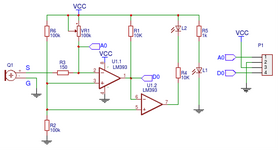
This is a circuit diagram of the sound detection sensor.

I know that when the signal goes in, D0 goes high, the output of the second comparator goes low, and LED2 turns on.

However, I don't really understand the operating principle.

First of all, here's what I thought:
When a sound occurs, the voltage entering A0 and the comparator input are divided into voltages. Therefore, I thought that if the variable resistance is large, A0 operates sensitively, and on the other hand, the signal entering the input of the comparator decreases, increasing the threshold value of the digital output.

I am not sure if the above interpretation is correct. If I'm wrong, I'd like to ask the following two questions.

1. I would like to know the principle of how A0 and D0 change as the variable resistance changes.
2. Ultimately, I would like to know how the threshold of the comparator is determined.
 

Attachments

  • 1713161732594.png
    1713161732594.png
    50.6 KB · Views: 38
The threshold is set at half supply voltage by the equal values of R2 and R6.
The principle of operation is that the voltage on U1-1 pin 2 is set very close to the threshold and the additional voltage from the microphone takes it over the threshold and makes the comparator change state. There is a fairly serious design flaw though, it relies upon the voltage on pin 2 being set by VR1 versus the current through R3 and the microphone. If VR1 is set to minimum value, only the R3 limits the microphone current and it will likely exceed the microphones rating and damage it. You do not mention the supply voltage but based on 10K in series with the LED I would guess it is relatively high so the chance of destroying the microphone is high.

Brian.
 
Hi,

I agree with Brian: it´s a poor design.

I just want to add to Brian´s information:
* Sound is AC. In the meaning of positive signal as well as negative signal.
And in your circuit it relies that VR1 is adjusted that A0 voltage is slightly above VCC/2. And now the noise level (amplitide) needs to be high enough
that the negative going microphone signal goes lower than VCC/2.
Then the LED becomes activated. But this will be true only for some 100us then the LED will be OFF again. Toggling maybe thousands of times per second.

So it´s not a clean "ON when sound is above threshold" and constantly ON as long as the sound exits, instead its a continous ON/OFF toggling.

May saying: A circuit without a capacitor is no reliably working circuit is true here.
When I think about a "sound detection circuit" I think about a circuit focussed on a limited range of frequency, involves filtering yout unwanted noise (ultrasonic, infrasonic, amplifier noise, ambient noise, power supply noise..) has a true schmitt trigger function that is ON as long as the tone exists.
But this is only my personal opinion -.. you might have your own requirements .. and maybe you are satsfied with the circuit.

Klaus
 
Presume Q1 is an electret microphone. Electret transducer has current source characteristic, as long as supply voltage doesn't exceed microphone voltage rating, there's no risk to damage it. Quiescent current is affected by temperature drift, AC coupling of microphone output will result in more stable threshold.
 

LaTeX Commands Quick-Menu:

Similar threads

Part and Inventory Search

Welcome to EDABoard.com

Sponsor

Back
Top