Continue to Site

Welcome to EDAboard.com

Welcome to our site! EDAboard.com is an international Electronics Discussion Forum focused on EDA software, circuits, schematics, books, theory, papers, asic, pld, 8051, DSP, Network, RF, Analog Design, PCB, Service Manuals... and a whole lot more! To participate you need to register. Registration is free. Click here to register now.

Sound Sensor schematic check

gvi70000

Member level 5
Joined
Sep 29, 2009
Messages
83
Helped
0
Reputation
0
Reaction score
1
Trophy points
1,288
Location
Romania
Activity points
1,920
Hi,

I am trying to make a sound sensor that will be used with a microcontroller.
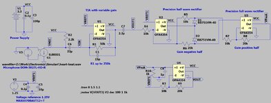
The first amplification stage is based on this document from TI with some modifications

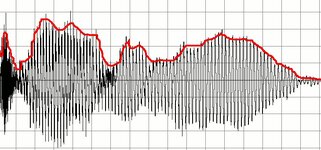
The second and third stage is a precision full wave rectifier that will act as envelope with the RC placed at input of last amplification stage, the output signal should be an envelope.
In LTSpice the simulation works well till I added the RC+last amplification stage and the program is crashing.
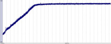
The goal is to get at the output a signal similar with the one shown in the last image.
Any idea what I am doing wrong in the schematic?
Any ideas or comments for improvement are welcomed.
 

Attachments

  • TIA mic calculation.jpg
    TIA mic calculation.jpg
    185.7 KB · Views: 70
  • Schematic.jpg
    Schematic.jpg
    178.8 KB · Views: 66
  • Envelope.jpg
    Envelope.jpg
    83.4 KB · Views: 70
Last edited:
Hi,

First stage: If it should work for very low signal levels you need a stable VBias (as with the light senesor).

But here it is different, because you don´t need to go down to DC. Here it´s a greater chance that VBias generated from VCC will work. It depends on the prcision you need.

***
For the rest: It depends what it is used for. If you don´t have very precise requirements as values with units... you are far more flexible to do all the processing stuff in software with a microcontroller.
It´s far more simple to adjust the software than to change the schematic and adjust part values.

Klaus
 
Your third image looks just like amplitude modulation (similar to the waveform as an AM radio station broadcasts). It has a carrier frequency modulated by your audio signal (envelope).

Yet you mention RC in the last stage. Do you intend for an RC filter to de-modulate the waveform?
De-modulation is normally achieved with a plain diode (or transistor). Then a capacitor (or RC filter) adjusted to smooth the gaps between carrier waveforms. Both R and C value must be carefully adjusted.

In simulation the capacitor may need for you to put a different low-ohm resistor in the same wire. Without a resistor the simulator may think it can't calculate a capacitive time constant (RxC). (And the result may be an error or crash.)
 
Hello all,
I have assembled the PCB and after first testing I can say something is wrong.
In the schematic R3 C4 are not populated, the jumper is closed.
As you can see the output of the sensor is increasing in time till a maximum value.
Any idea why?
 

Attachments

  • SoundV5.pdf
    69.6 KB · Views: 59
  • AnalogRead.jpg
    AnalogRead.jpg
    121 KB · Views: 49
Hi,

You say "the output of the sensor is increasing"..

Where exactly do you measure "the output of the sensor".

A photo of the PCB with your measurment connections will be helpful.

Klaus
 
Vref2 is going up to 3.06V
Hi,

You say "the output of the sensor is increasing"..

Where exactly do you measure "the output of the sensor".

A photo of the PCB with your measurment connections will be helpful.

Klaus
Hi,
The B2 or READ_SEN is going into the ADC of the microcontroller.
"the output of the sensor is increasing" I was referring to ACD readings, they are suppose to stay relative stable at a lower value.

I do not understand why the VREF2 starts at 0.5V but it slowly going to 3V.
 

Attachments

  • Output.jpg
    Output.jpg
    15.1 KB · Views: 48
Not necessary the reason for wrong Vref2, but according to datasheet ADR130 maximal load capacitance is 1 uF where you have 10 uF. It could be a hidden oscillation.
 
Hi,

Same situation repeated:
Now you say "VRef2 starts moving" ... but no information where you measure it and how.
DVM, scope, ADC ....?

Use a scope and first check supply voltage stability.
Then use the scope and step by step check the signals from output back to to signal input.

Yes: very important information missing: what exactly is connected at the input?

Don't give piece by piece informations. Alwas add: why and how and where.

Klaus
 
Hello all,

Thank you for your feedback.
I have manage to debug the board and the digital potentiometer was damaged (I guess I have soldered and disordered too many times), now everything works as expected.
 

LaTeX Commands Quick-Menu:

Similar threads

Part and Inventory Search

Welcome to EDABoard.com

Sponsor

Back
Top