Continue to Site

Welcome to EDAboard.com

Welcome to our site! EDAboard.com is an international Electronics Discussion Forum focused on EDA software, circuits, schematics, books, theory, papers, asic, pld, 8051, DSP, Network, RF, Analog Design, PCB, Service Manuals... and a whole lot more! To participate you need to register. Registration is free. Click here to register now.

Light Sensor schematic check

gvi70000

Member level 5
Joined
Sep 29, 2009
Messages
83
Helped
0
Reputation
0
Reaction score
1
Trophy points
1,288
Location
Romania
Activity points
1,920
Hello all,

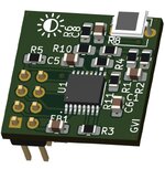
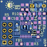
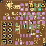
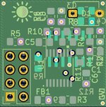
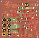
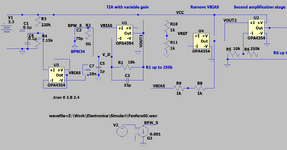
I need your help in checking the attached schematic before I will send the PCB to manufacturing.
The idea behind it is to have a variable sensitivity sensor that will feed the ASC of a microcontroller.
As sensitive element I am using a BPW34 PIN photodiode. The current generated is fed into a TIA that has a variable gain set by the digital pot.
For it to work when no current is flowing I have used a small voltage bias.
In the second stage I am removing the bias from the TIA output.
The third stage is again an amplifier to be able to amplify very weak signals.
The last stage is a buffer and I am using R12+C6 to smooth the output signal.

Please let me know your opinions, will the circuit work as described? Do you have any improvements to propose?

Thank you for your support,
Ion
 

Attachments

  • LightSensor.pdf
    60.8 KB · Views: 104
Hi,

I'd use two Opamps max.
Every Opemp adds noise, nonlinearity, distortion, offset, and drifts.

I'd avoid using VCC as VRef, Vcc is noisy and not stable over time, temperature and load current.

1pF in my eyes is not suitable, not in the feedback, nor in parallel to the photodiode. I'd omit it in parallel to the photodiode at all.
In the feedback I'd use 30pF minimum if you need high frequency ... and up to some nF if you are interested in lower frequency.
Tell us your signal requirements, like signal bandwidth...

I recomend to decide/calculate what signal range you are interested in. "Weak" is not descriptive.

The output of the second stage is not weak. Adding a buffer doesn't make it stronger. But adding 100 ohms at the very last stage makes the signal weak and prone for noise.

ASC? ... I guess you mean ADC. Please confirm.

Your "bias" voltage is weak. It has a source impedance of about 7k. But then you load it with 1k (R8) to a variable signal. I guess the result will not be what you expect. In worst case it may lead to oscillation.
Better use one Opamp to generate a strong Vbias.

Klaus

Added: you talk about a PCB ... but didn't show us. The PCB layout will have a lot of impact on overall performance.
 
"The idea is to have blah-blah..." makes me think you are ignoring
the application in favor of a specific and elaborate solution.

You then proceed to say you are doing all of these things but not
word one about why.

Looks to me like you'll be integrating daylight against an arbitrary
reference. I'll call it a full-on fail. It's certainly much more complex
than a "presence / absence of light above threshold" sensor
warrants, but too squirrely to be anything quantitative or field-
repeatable.

If this is a for-real effort to make working hardware, then this PDF
is supposed to document a working prototype. Did the prototype
work?

For basic detection you could do the job with a NPN, a resistor,
a trimpot and your photodiode, off the uC I/O supply and feed
the output to a regular I/O. But you never mention just what this
tray of parts is really meant to do so it's just a guess and not
what you asked for.
 
Hello Klaus and Freebird,

This sensor will be used as an input to an analog pin of a micro controller (ADC not ASC) that will control a photo camera shutter an focus.
I intend to use the sensor at night to detect small variations in light, as well in daylight. The signal from the analogue output is presented to the user and he is deciding if the camera shall trigger above/below a threshold value he will set.

The "strength" of the photodiode signal most likely will go from 40nA to 20uA (this is a guess), I have measured 30nA on the photodiode in a complete dark room and 220nA in a room during cloudy day.

Related to bandwidth, using the 1pF in the feedback loop (W1-B1) the worst case will be when the resistance between the 2 terminals is 250k, 636.6kHz and the best case is at 10k with 15.9MHz.

In my specific application I think the bandwidth is not something to worry about.

The buffer was added because "why not? I have a spare op amp" but I guess I can use it as Vbias.
R12+C6 was intended to make the output signal a bit smoother.

I do not have a prototype yet, I intend to order a PCB as soon I am very confident that this will work.

I am using OPA4354 as I already have several parts, so I have access to 4 op-amps.

Let me know if more information is needed.
 

Attachments

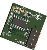
  • Bottom-3D.jpg
    Bottom-3D.jpg
    89 KB · Views: 55
  • Top-3D.jpg
    Top-3D.jpg
    88.2 KB · Views: 63
  • Bottom-4.jpg
    Bottom-4.jpg
    143.9 KB · Views: 53
  • VCC-3.jpg
    VCC-3.jpg
    129 KB · Views: 52
  • GND-2.jpg
    GND-2.jpg
    122.7 KB · Views: 52
  • Top-1.jpg
    Top-1.jpg
    133.8 KB · Views: 50
Hi,

My personal opinions:
* I guess the bandwidth depends on how fast the light conditions change. 10Hz could be sufficient ... go higher to be on the safe side. But keep it low to keep the noise low.
* use a fixed known sampling rate on the microcontroller, so you can desingn a suitable anti aliasing filter ... as well as digital filters.
* apply digital (notch) filters for mains powered "artifical light sources" like neon and LED. Mains frequency and (more important) twice the mains frequency.
* using two 10 bit gain adjustments combined with an 10+ bits ADC is complete overkill (30 bits overall). You gain nothing meaningful. If you use the 40nA as step size, then you just have 1:500 = 9 bits dynamic for the 20uA range you expect. Ambien light is rather dynamic. So I guess you need to focus on the dark. So even if you go down to a 1nA resolution, then a 1 bit ADC will have 1uA full range. So a simple "gain of 50" switch should cover up to 50uA.
(it makes no sense to adjust the (ADC) resolution from 10.00nA to 10.01nA (using just one pot).

In my specific application I think the bandwidth is not something to worry about.
I don´t agree. I see you want good performance. But if your noise is higher than your ADC resolution, then you lose information. From your higher (above nyquitst) frequency noise you get lower frequency alias noise you can´t get rid of on the digital side.
It´s wrong to just consider resolution, you need to focus on "quality of information" which more relates to "signal-to-noise" ratio.

The buffer was added because "why not?
Why not: Because of:
* zero improvement
* but adding errors.
The result is worse than without it.
My counter question: Why making the signal worse?

R12+C6 was intended to make the output signal a bit smoother.
"Smoother" in technical terminology means "low pass filtered". And due to the series resistance it becomes weaker, more prone to external influence.
My question. Why not filter the signal on the OPAMP input? Then it is both, smooth and "strong".

Such RCs at the output of an OPAMP makes sense if you want to supply a SAR ADC with unbuffered input where you have to feed switched capacitors (inside the ADC). These switched capacitors cause current peaks that may cause ringing at the OPAMP output. Check what ADC you have. Still then the peforms better on the ADC side than on the OPAMP side.

***
The OPAMP is noisy, especially the voltage noise. 8uV pp may equal to maybe more than 45uVpp.
4 Stages in series, each with some gain ... results in the noise at the ADC input to be more than 1 LSB. Decreasing the overall performance.

Don´t get me wrong. You can do whatever you want and I don´t want to discourage you. All above is just my personal view.
Measurement for me is nothing emotional, it follows physical rules. Quite good to calculate.
For me - with decades of professional experience in designing analog and digital measurement equippment ...
I understand your ideas, but the current design more works against the ideas than to support them.
You get better performance if you apply useful filters and keep the (Opamps) circuit simple.
OPAMPs are a good thing, but only if used properly.

Klaus
 
Hello Klaus,
Thank you again for your feedback.
The ADC resolution on the MCU is 12 bits.
I do not wat to process the signal on the MCU as it is busy doing something else.

The sensor should be able to detect lightings in day light as well during the night and also to to act as a photogate (if a light beam is interrupted).

During the night it should be able to detect variation in light intensity (to detect meteors) using a 60mm lens on top of the photodiode.

When I was referring to "smoother" I was thinking at an envelope follower - I am not sure if is needed, I do use it on a sound detector sensor(based on this feedback I will have to remake that sensor design also, most likely I will post it here).

I have implemented your suggestion related to V Bias using one op amp.
Is not an issue for me to use less than 4 Op amps of the OPA4354.


I forgot to mention that I am not an electronics expert so my knowledge and understanding is limited.
I am open to any suggestions coming from experts, this is the reason I asked support here.
 

Attachments

  • OpAmpBias.png
    OpAmpBias.png
    58.5 KB · Views: 54

Attachments

  • photodiode-amplifiers-op-amp-solutions_compress.pdf
    54.5 MB · Views: 70
Hi,

I do not wat to process the signal on the MCU as it is busy doing something else.
This surely kills your performance regarding signal quality.
Relying on a single (noisy) sample .. is something I avoided since decades now. Using digital filtrs you may easily get less than 10% noise. No "ADC resolution" nor "gain adjustment" can improve this.
I did recommend continous sampling and digital filtering. Let´s say you do continous sampling with 600Hz (for simple 50Hz, 60Hz, 100Hz, 120Hz mains filters) and second order low pass filtering I guess it uses
less than 1/1000 of processing power of an STM32...
So if your microcontroller is busy for 80% of the time (don´t go higher), then it will be 80.1% including digital filters.

Using VCC as VBias surely kills your performance. You can´t rely on the "low light information" because it is overruled by Vcc noise (multiplied by the BPW_capacitance and multiplied by noise frequency)

Completely "Removing VBias" will kill your "low light information", because of unknown offset voltage and offset current of the OPAMPs, Output_Low_level_performance of the OPAMP and because the OPAMP can regulate only in one direction on thus close to zero levels. Thus even noise will cause fluctuating offset - even when you average your ADC values.

Mind not to leave the inputs of the unused OPAMP floating.

During the night it should be able to detect variation in light intensity (to detect meteors) using a 60mm lens on top of the photodiode.
You can surely forget about this with your design. Sorry for being honest in this, but I want to prevent you to become disappointed later.
Maybe you find it hard to belive in me in this. I completely understand.
It´s hard to believe, because your eyes are able to detect those meteors even without lens.
But the your eyes do an extremely good job regarding light intensity dynamics. And your brain does an extremely good job in detecting moving objects.
So the technical/electronics solution is extremely difficult to come close to human performance.
You need good DC performance but even more you need low_noise, low_drift performance.
Indeed for detecting meteors you need detect currents in the low picoamperes.
Again: no additional OPAMP will be a benefit, and no gain fine tuning (using pots) will be a benefit.

To validate what I just wrote, please do some calculations on your own. It will help you to understand the physics and decide the circuit requirements.

Klaus
 
Hi,


This surely kills your performance regarding signal quality.
Relying on a single (noisy) sample .. is something I avoided since decades now. Using digital filtrs you may easily get less than 10% noise. No "ADC resolution" nor "gain adjustment" can improve this.
I did recommend continous sampling and digital filtering. Let´s say you do continous sampling with 600Hz (for simple 50Hz, 60Hz, 100Hz, 120Hz mains filters) and second order low pass filtering I guess it uses
less than 1/1000 of processing power of an STM32...
So if your microcontroller is busy for 80% of the time (don´t go higher), then it will be 80.1% including digital filters.

Using VCC as VBias surely kills your performance. You can´t rely on the "low light information" because it is overruled by Vcc noise (multiplied by the BPW_capacitance and multiplied by noise frequency)

Completely "Removing VBias" will kill your "low light information", because of unknown offset voltage and offset current of the OPAMPs, Output_Low_level_performance of the OPAMP and because the OPAMP can regulate only in one direction on thus close to zero levels. Thus even noise will cause fluctuating offset - even when you average your ADC values.

Mind not to leave the inputs of the unused OPAMP floating.


You can surely forget about this with your design. Sorry for being honest in this, but I want to prevent you to become disappointed later.
Maybe you find it hard to belive in me in this. I completely understand.
It´s hard to believe, because your eyes are able to detect those meteors even without lens.
But the your eyes do an extremely good job regarding light intensity dynamics. And your brain does an extremely good job in detecting moving objects.
So the technical/electronics solution is extremely difficult to come close to human performance.
You need good DC performance but even more you need low_noise, low_drift performance.
Indeed for detecting meteors you need detect currents in the low picoamperes.
Again: no additional OPAMP will be a benefit, and no gain fine tuning (using pots) will be a benefit.

To validate what I just wrote, please do some calculations on your own. It will help you to understand the physics and decide the circuit requirements.

Klaus
Thank you Klaus,
Before I will go back and rethink everything I have 2 questions.
1. What is the value you would suggest for V Bias?
2. Do you think it makes sense to keep the "Remove Bias" op amp stage?

I am asking this because I have already a MCU board with STM32F722 that I can use for digital signal processing.
 
Last edited:
Step of 1 uA seemes reasonable at TIA output :

View attachment 184523

Meteor detection DIY


I thought this was interesting :


Regards, Dana.
Thank you for your feedback Dana.
Right now I am going through the book you have sent
 
Last edited:
Hi,
1. What is the value you would suggest for V Bias?
The value - I think - is not that important. I´d try something between 0.3V and 1.0V.
But it needs to be stable and free of noise. That´s more important.
--> I recommend to use a so called "voltage reference".

2. Do you think it makes sense to keep the "Remove Bias" op amp stage?
Reduce it, but not completely remove it. It needs to be high enough for
* The opamp to work properly (DC accruate)
* to care about the Opamp´s offset errors
* the ADC input offset error
* to care about PCB and part leakage/stray currents
--> i´d not go below 20mV (rather 50mV) for each OPAMP input, OPAMP output and ADC input.

***
I had a similar project for an X-Ray detector based on a PIN diode. ADC resolution down to 3pA (@ the sensor) and trigger down to 60pA - if I remember right. A max range of about 500uA. TIA, then one Opamp for four gain ranges: 1 - 16 - 256 - 4096, 16 bit ADC @ 10kSmpl/s.

Klaus
 
Strictly for future work, given that you picked your processor, consider using a SOC like PSOC 5LP.
Here is whats on the chip, multiple copies in most cases. A onchip resource is called a component in
PSOC lingo :

1692540909263.png

Here is example possibility for your design, including a onchip 60 Hz filter (uses just a fraction of
onchip resources) :

1692540969175.png


1692541315706.png


I added the onchip TIA and PGA, but did not wire (route) them up, as shown above. Single chip.
Note I did not moid the project example of filter, the input side, to handle your photo sensor.
But its capable of CM outside rails by 100 mV, and direct connection to sensor.

IDE (PSOC Creator) and compiler free, board to start with $ 15, CY8CKIT-059.


Regards, Dana.
 
Last edited:
Strictly for future work, given that you picked your processor, consider using a SOC like PSOC 5LP.
Here is whats on the chip, multiple copies in most cases. A onchip resource is called a component in
PSOC lingo :

View attachment 184530
Here is example possibility for your design, including a onchip 60 Hz filter (uses just a fraction of
onchip resources) :

View attachment 184531

View attachment 184532

I added the onchip TIA and PGA, but did not wire (route) them up, as shown above. Single chip.
Note I did not moid the project example of filter, the input side, to handle your photo sensor.
But its capable of CM outside rails by 100 mV, and direct connection to sensor.

IDE (PSOC Creator) and compiler free, board to start with $ 15, CY8CKIT-059.


Regards, Dana.
Thank you very much Dana for your effort and great feedback.
 
Just as an aside, the SOC runs the filter, A/D, in a DMA process all run in HW, onchip ARM
CPU not involved other than whatever you are doing with measurement.

Regards, Dana.
 
Hello Klaus and Dana,

I have decided to use the attached schematic and the reasoning behind is the following:
1. Using a voltage reference will increase the cost and I am not able to buy parts locally at a reasonable price. Instead I am using 1 of the 4 op-amps to create a bias voltage using 0.1% resistors.

2. I have kept C1 in parallel with the photodiode - I can cut the traces if needed.
3. I will experiment with C3 values
4. Use one op-amp as subtractor to remove the bias voltage
5. Added filter before second amplification stage - to be used as optional

After reading the book Dana provided and considering the complexity of my project I have decided that a general purpose light sensor is the way to go.
Please let me know if this schematic is good enough for a general purpose light sensor.

Thank you very much for your support.
 

Attachments

  • LightSensor.pdf
    67.3 KB · Views: 71
Hi,

I tried my best to support you with your project.
After reading post#17 I guess I failed in in almost every single point. Sorry for this.

Klaus
 
Hi,

I tried my best to support you with your project.
After reading post#17 I guess I failed in in almost every single point. Sorry for this.

Klaus
Hello Klaus,
Sorry for disappointing you, this was not at all my intension. I will try to find a reference voltage IC and I will come back with a different design.
Ps: Do you have any suggestion for such IC? I will need one for my sound sensor as well. I have found REF7012 is this a good choice?
 
Last edited:
Hi,

I tried my best to support you with your project.
After reading post#17 I guess I failed in in almost every single point. Sorry for this.

Klaus
I just realize that the price of the TI IC is very high so I was looking at ADR130BUJZ for Light sensor and MAX6070BAUT12+T for the sound sensor
 

LaTeX Commands Quick-Menu:

Similar threads

Part and Inventory Search

Welcome to EDABoard.com

Sponsor

Back
Top