Continue to Site

Welcome to EDAboard.com

Welcome to our site! EDAboard.com is an international Electronics Discussion Forum focused on EDA software, circuits, schematics, books, theory, papers, asic, pld, 8051, DSP, Network, RF, Analog Design, PCB, Service Manuals... and a whole lot more! To participate you need to register. Registration is free. Click here to register now.

[SOLVED] some questions motor speed monitoring

Status
Not open for further replies.
screen printing is something that the pcb manufacturer prints the legen on the board like R1,r2,..... c1, c2..... in the same way i though if you get your board printed with version number as 1.0 and next version as 1.1 it will be easy in future for you to keep track of which version had which features .. if you plan to market and sell it then definetely you may have some modifications in the board... if you keep it in version numbering the boards it will be easy to track.... the printing of words on the board is called screen printing....

though off topic .. i gave this suggestion... i am not aware of the other post by other friend...
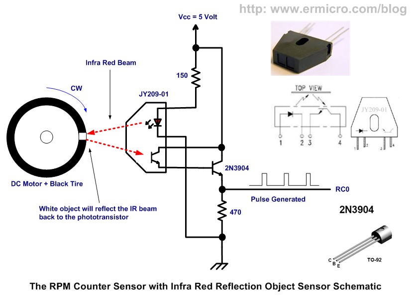
 
More impt . than going to details of screen printing is the issue of pulsewidth needed for the rotating axle so that detection of signals is positive ..kindly make the sense width from the detector output sufficiently wide and the decay of pulses as overdamped .
 

pic18_pwm_11.jpg


why does this sensor always detect every object even it's not reflective?

the output status always toogle if whatever object I place in front.. I thought the infrered sensor will only turn on if the object is reflective..
 

Hi Romel,

The IR Sensor should be able to differentiate between a black and white surface if configured correctly.

I found the example project which uses your IR Sensor:

PIC18 Pulse Width Modulation (PWM) DC Motor Speed Controller with the RPM Counter Project

Have you double checked your connections and component values?

What are the distances from the test objects the IR Sensor output level transitions to high?

What type of objects have you used to test the IR Sensor?

BigDog

It's now working all the problem was about the object sensed.. I created a cylindrical shape object covered by black tape and I added a mirror like stripe to interrupt the signal.


I made something like this

4170765217_c66f1acb59.jpg


but I will try it tomorrow.

here what I made.. hehe

will try it in the morning
 

Attachments

  • 3.JPG
    3.JPG
    5.8 KB · Views: 75

You might generate a better pulse with a bright white strip instead of a reflective or mirror finish, which it looks like you are using.

Remember mirrors reflect visible light, not necessarily IR light, it depends on the materials IR reflectivity.


BigDog
 
I will replace it if will not satisfy my expected outcome..

the logic of my circuit is the output is always high and it will only gets low if the IR reflects .. I already tried it in my small motor..
 

now working well.. hehe Thanks guys.
**broken link removed**
 

I have question.. I displayed the floating number of adc using this code..

is there any trick that I could display floating point from the result of this computation?

PHP:
res = (res * 4.8)/1023 * 3.135;

bigdogguro said that I must avoid using float in 8bit MCU.. hehe :) I declared res as float so that I can get the floating point... is there any other way of doing this?


PHP:
void display_data(float res)
{
	
	float ftemp1,ftemp2;
	char ADC[2];
	int temp1,temp2;
	
	lcd_cmd(0xC0);
	lcd_str("VOLT:");
	lcd_cmd(0xC8);

	res = (res * 4.8)/1023 * 3.135;
	if(res < 10)
	{
			
			
			ftemp1 = (res * 100) / 100;
			temp1 = (unsigned int)(ftemp1 * 10) % 10;
			lcd_data(ftemp1+48);
			lcd_data('.');
			lcd_data(temp1+48);
			
			
			if(r==1)
			lcd_str("     ");			
			r = 0;
			
	}
	else
	{
			
			ftemp2 = (res * 100) / 100;
			temp2 = (unsigned int)(ftemp2 * 10) % 10;
			long_to_string(ftemp2,ADC,2);
			lcd_str(ADC);
			lcd_data('.');
			lcd_data(temp2+48);
			r = 1;
	}
	res = 0;

}


---------- Post added at 10:44 ---------- Previous post was at 10:43 ----------

Very nice.

Did you end up using the mirrored reflective strip or something else?

BigDog


I did not tried the mirrored one I just followed directly your instruction.. hehe :)
 

A small note

ftemp1 = (res * 100) / 100; is the equivalent of ftemp1 = res; ;-)

I'm trying to figure the exact calculation that you are trying to do, what is res = (res * 4.8)/1023 * 3.135;

I don't think you should use float variables, you can probably replace all the numbers with integers (using a multiplier)
also I don't think that long_to_string(ftemp2,ADC,2); will work correctly with a float

Alex
 

I have question.. I displayed the floating number of adc using this code..

is there any trick that I could display floating point from the result of this computation?

PHP:
res = (res * 4.8)/1023 * 3.135;

bigdogguro said that I must avoid using float in 8bit MCU.. hehe :) I declared res as float so that I can get the floating point... is there any other way of doing this?

Actually I said you should avoid floating point arithmetic when possible.

There are several different techniques to confine your calculation to the use of only integers.

Integer math, scaler and fixed point are some of the most commonly used.

The following PDF demonstration the use of Integer and Scaler Math to calculate the voltage at an ADC channel:

ADC SCALER METHOD

Hope you find the method interesting,

BigDog
 
I don't think you should use float variables, you can probably replace all the numbers with integers (using a multiplier)
also I don't think that long_to_string(ftemp2,ADC,2); will work correctly with a float

I just used the long_to_string to display the value above 9 and below 100 but my adc will just read up to 15v. :)


ftemp1 = (res * 100) / 100; is the equivalent of ftemp1 = res;
no it's not the same adc value below 10 will not display if I do that.. I dont know how I come up with this lines I just calculated manually then translate to program.. hehe

I will attached proteus file and hex.. it's working that way..
 

Attachments

  • motorRPM.rar
    256.8 KB · Views: 73

res = (res * 4.8)/1023 * 3.135;

this calculation is for scaling my aDC input. res will be from 0 - 15v

4.8 is max voltage divider output.
3.135 = 15v/4.8VinMax of ADC;
1023 - resolution of my ADC


actually, if you still remember you're the one who taught me this method... :)

---------- Post added at 11:55 ---------- Previous post was at 11:41 ----------

Actually I said you should avoid floating point arithmetic when possible.

There are several different techniques to confine your calculation to the use of only integers.

Integer math, scaler and fixed point are some of the most commonly used.

The following PDF demonstration the use of Integer and Scaler Math to calculate the voltage at an ADC channel:

ADC SCALER METHOD

Hope you find the method interesting,

BigDog


Thanks so much.. downloaded.. I will study this
 
Last edited:

I just used the long_to_string to display the value above 9 and below 100 but my adc will just read up to 15v. :)

ftemp1 = (res * 100) / 100; is the equivalent of ftemp1 = res;

no it's not the same adc value below 10 will not display if I do that.. I dont know how I come up with this lines I just calculated manually then translate to program.. hehe

in this case you have float1 = (float2*100)/100 , how is this different from float1 = float2?
if res=8 then 8*100=800/100=8
if res=8.05 then 8.05*100=805/100=8.05

I can't see what you mean or get any different result from the initial value of res

Alex
 

hehe I was wrong.. :smile: :smile: :smile: :smile: :smile:

:smile: :smile: :smile: :smile: :smile:

here is your correction.. I realized I was repeating my steps.. hehehe :smile: :smile: :smile: :smile:

PHP:
void display_data(float res)
{
	
	char ADC[2];
	int temp1,temp2;
	
	lcd_cmd(0xC0);
	lcd_str("VOLT:");
	lcd_cmd(0xC8);

	res = (res * 4.8)/1023 * 3.135;
	if(res < 10)
	{
			
			
			temp1 = (unsigned int)(res * 10) % 10;
			lcd_data(res+48);
			lcd_data('.');
			lcd_data(temp1+48);
			
			
			if(r==1)
			lcd_str("     ");			
			r = 0;
			
	}
	else
	{
			
			temp2 = (unsigned int)(res * 10) % 10;
			long_to_string(res,ADC,2);
			lcd_str(ADC);
			lcd_data('.');
			lcd_data(temp2+48);
			r = 1;
	}
	res = 0;

}
 

The precedence of * / % operators is the same (C Operator Precedence Table) and they execute from left to right so your code executes the calculation in the correct order but I would generally use the parenthesis (even when they are not needed) to makes the code easier to read and in some cases save you hours of debugging.

res = ((res * 4.8)/1023) * 3.135;

but more importantly you can have the same result (more accurate actually) without any float involved, just use res = (res * 15)/1023;
if you use res = (unsigned int)(((unsigned long)res * 15000)/(unsigned long)1023); you can get a result that is in mV and always an integer (0 to 15000)

Alex
 
See if you can put a slip of red color cellophane sheet between the transistor and the axle rotor .
All visible light will cutoff and sensor noise will reduce faulty /oversensitive detection.
 

See if you can put a slip of red color cellophane sheet between the transistor and the axle rotor .
All visible light will cutoff and sensor noise will reduce faulty /oversensitive detection.

you mean between the sensor and the object?

by the way this is the working video of this project
 

Status
Not open for further replies.

Similar threads

Part and Inventory Search

Welcome to EDABoard.com

Sponsor

Back
Top