Continue to Site

Welcome to EDAboard.com

Welcome to our site! EDAboard.com is an international Electronics Discussion Forum focused on EDA software, circuits, schematics, books, theory, papers, asic, pld, 8051, DSP, Network, RF, Analog Design, PCB, Service Manuals... and a whole lot more! To participate you need to register. Registration is free. Click here to register now.

[SOLVED] some questions motor speed monitoring

Status
Not open for further replies.
So are you still in the software design stage or are you going to implement it with hardware?

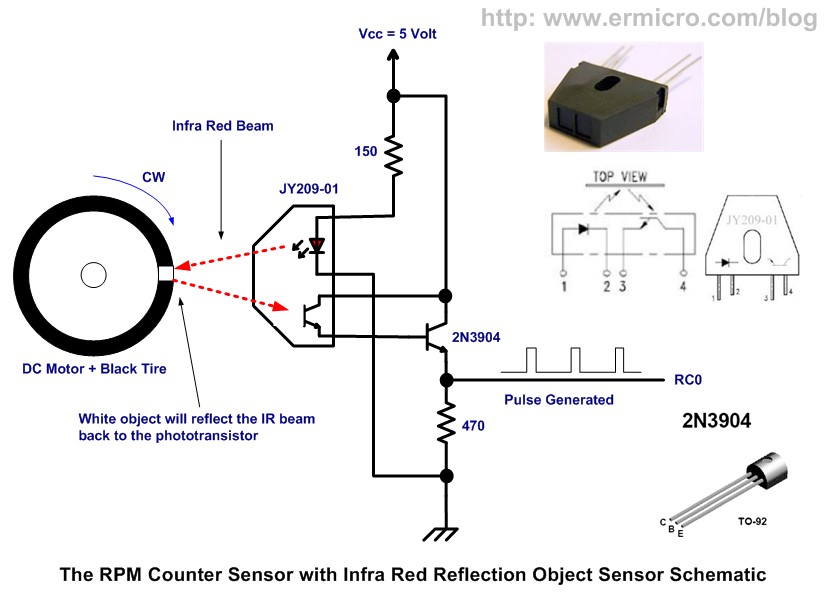
If you are going to construct your design, have you decided on your sensor type?

IR sensor is nice but I will check first what is available in my market. I will going to implement this in hardware. next of this I will study eagle cad software how to design a small PCB for this project. but not for now because tomorrow I will study my FPGA subject


do you have suggestion of the hardware to be use? thanks.
by the way, the minimum RPM I can measure is 0.5Hz I think... I dont know the formula.. hihi :) and how to get the maximum? hehe
 

do you have suggestion of the hardware to be use? thanks.

Depends on circumstances by which you are taking the measurement. Optical sensors like IR work well with fans, gears, etc attached to the motor shaft, although you can make a simple optical encoder with you can fasten on to a shaft fairly easy.

While Hall sensors work well when there no devices fastened on to the motor shaft that are readily visible, like a shaft going into a gearbox.

I see if I can find a supply shop in your area which carries inexpensive optical encoders which will fasten onto one of the standard shaft sizes.

by the way, the minimum RPM I can measure is 0.5Hz I think... I dont know the formula.. hihi :) and how to get the maximum?

You should be able to calculate the min and max from your algorithm implemented in your code. I'll take a look and see if I can give you the theoretical range.

The minimum of 0.5 RPM is definitely low enough for most applications.

BigDog
 
There is no need to clamp any physical attachment on the axle/rotor or any moving element .
Just a white mark /reflective line that the optical reflections will show as a sharp pulse .
These are used for trigger sync operation.
 

I looking for a nice Brushless DC motor (BLDC) with an encoder or hall sensor which you can pickup cheap.

**broken link removed**

Something like the above example, but who will ship to your area.

BigDog
 

There is no need to clamp any physical attachment on the axle/rotor or any moving element .
Just a white mark /reflective line that the optical reflections will show as a sharp pulse .
These are used for trigger sync operation.

yes... the idea is the IR got a reflection from the reflective thing in the rotor..

I have question since I dont know much about IR. does the IR not affected in sunlight e.g. the motor is place outside under the heat of the sun... hehe
 

I have done this for 2880 rpm in a double bearinged high CFM fan for eddycurrent 5KW drive as well as stepper motors
which go for linear movement sensors for CNC machine.
The geared down movement is barely 1 rpm.
Both cases work without errors .
However , the rotor needs to be physically seen and open to eye .not encased within a casting .
Open to weather /sunlight poses no problems to IR LEDs or even UV LEDS so long as it is in shade.
The temp rise affects of GaAsP material is 2mV per Deg C .And 55*C rise in India (semi arid condns) has no effect
as there is a differential rise in transmitter /receiver LEDs .
 

There is no need to clamp any physical attachment on the axle/rotor or any moving element .
Just a white mark /reflective line that the optical reflections will show as a sharp pulse .
These are used for trigger sync operation.

Not if the shaft is reflective itself, which most are.

You could attempt to place a black stripe along the shaft. But if you're going to develop motor control designs it's worth picking up an encoder or Hall sensor.

You can easily buy a nice BLDC with encoders or sensors in the $15 to $20 range. Like the example above.

BigDog
 

I looking for a nice Brushless DC motor (BLDC) with an encoder or hall sensor which you can pickup cheap.

**broken link removed**

Something like the above example, but who will ship to your area.

BigDog

$16 * 44 = 704php in my currency.. :)

no need to buy This is just my adventure I have here a motor from old toy car.. :) LOL
 

yes... the idea is the IR got a reflection from the reflective thing in the rotor..

I have question since I dont know much about IR. does the IR not affected in sunlight e.g. the motor is place outside under the heat of the sun... hehe

It largely depends on the active spectrum of the device, certain wavelengths are not very prominent in sunlight. You can also place a directional hood over the sensor.

---------- Post added at 08:27 ---------- Previous post was at 08:21 ----------

no need to buy This is just my adventure I have here a motor from old toy car..

Save the gear on the shaft and you can use it for an optical encoder. A little paint and marker.
 

It largely depends on the active spectrum of the device, certain wavelengths are not very prominent in sunlight. You can also place a directional hood over the sensor.

---------- Post added at 08:27 ---------- Previous post was at 08:21 ----------


Save the gear on the shaft and you can use it for an optical encoder. A little paint and marker.

check this: **broken link removed**

Affordable price here..

pic18_pwm_11.jpg
 
Yes, the sensor you have posted above would definitely work for your application. Maybe you could paint the gear black on the motor you have and place a piece of thin white tape for the reflective mark.

BigDog
 

Yes, the sensor you have posted above would definitely work for your application. Maybe you could paint the gear black on the motor you have and place a piece of thin white tape for the reflective mark.

BigDog


and also I revised the code and it gives me and exact result than my previous code.
my previous code @10Hz give me 450 to 540RPM but this one it gives me the same RPM with my calculation.


PHP:
void interrupt capture()
{
	static bit pulse_state = 0;	
 
	if(TMR1IF)
	{
		TMR1 = 0;
		TMR1IF = 0;
	}

	if(CCP1IF)
	{
		switch(pulse_state)
		{
			case 0: 
			TMR1 = 0;
			pulse_state = 1;
			break;

			case 1:
			rpm_timer = TMR1L;            // Get the first 8-bit TIMER0 Counter
        	rpm_timer += (TMR1H << 8);    // Get the last 8-bit TIMER0 Counter
			countrev = (int) (60000.0 / (0.008 * rpm_timer ));
			pulse_state = 0;


		}
		CCP1IF = 0;
		//PORTB = ~PORTB;

	} 
		

}


---------- Post added at 03:28 ---------- Previous post was at 03:24 ----------

and also noticed in the result it gives me accurate result by doing this one

PHP:
rpm_timer = TMR1L;            // Get the first 8-bit TIMER0 Counter
rpm_timer += (TMR1H << 8);    // Get the last 8-bit TIMER0 Counter


but if this one the result is less than 120 from the expected result

PHP:
rpm_timer = TMR1;


what is the difference of above and below code? I mean why method 1 give accurate result?

---------- Post added at 03:31 ---------- Previous post was at 03:28 ----------

I want to know the reason behind the scene ..hehe :p:p:p
 
Last edited:
Your geared motor with worm reduction could not be higher than 2880rpm.As such any thin white line less than 0.5mm will raise the trigger pulses .
The higher pulse rates only limit the monoshot you use for f to v determination.After the installation and pulse generation ,just close the cover and all sensor will be protected from sun rays and threshold noise
 
when you get screen printed.. it is better to print the version number too as in future if this may undergo changes ... it will help you to trace back features as per version number.....
 

Status
Not open for further replies.

Similar threads

Part and Inventory Search

Welcome to EDABoard.com

Sponsor

Back
Top