wandola
Junior Member level 3
I have designed a digital block circuit layout by SoC encounter. I've tried to export the layout into a GDSII file. After that I would import the GDS into cadence virtuoso to combine with my analog layout.
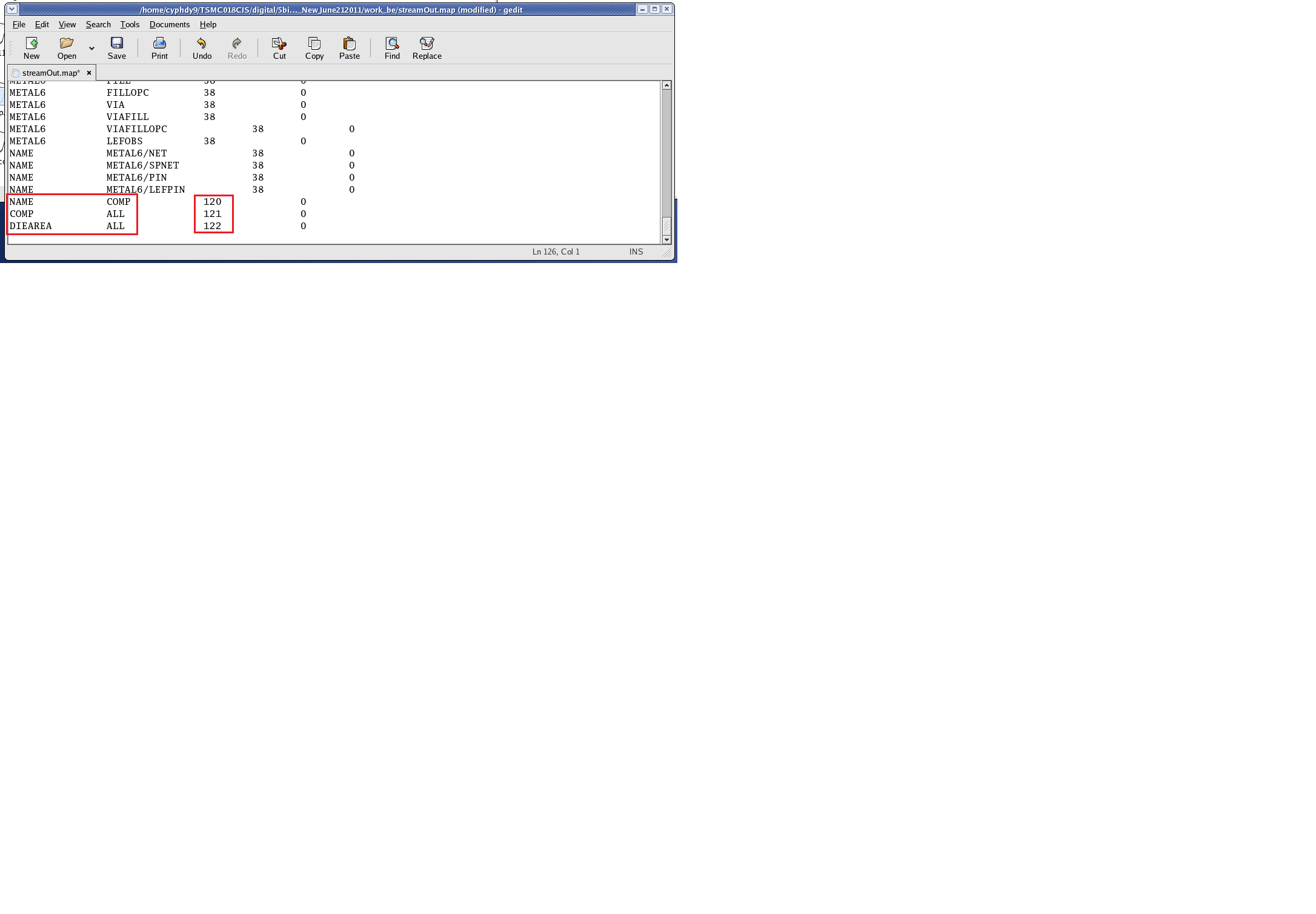
I have some problems with the Encounter layout exporting. The streamout.map file is generated by the Encounter software. But the layer number is not matched with the number provided by foundry.
What I did is to change the number to the correct number which is given by the foundry map file. The foundry map file is given by the PDK.
However, I still have several parameters unknown. Please see attached picture.
The last three parameters are not found in the foundry map file. So the numbers are unchanged. As a results, the generated gds file is not complete.
Does anybody know these parameters? Can anyone help me with this? I've been working on this for two weeks...
thanks a million....