Continue to Site

Welcome to EDAboard.com

Welcome to our site! EDAboard.com is an international Electronics Discussion Forum focused on EDA software, circuits, schematics, books, theory, papers, asic, pld, 8051, DSP, Network, RF, Analog Design, PCB, Service Manuals... and a whole lot more! To participate you need to register. Registration is free. Click here to register now.

Single-phase asynchronous motor control-circuit?

Status
Not open for further replies.

peterl86

Junior Member level 1
Joined
Apr 8, 2009
Messages
15
Helped
1
Reputation
2
Reaction score
1
Trophy points
1,283
Activity points
1,384
Hi guys,
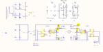
i want to make motor RPM controller for Single-phase asynchronous motor.The motor is 750W, running at 220V/50HZ.I think that power part should be with H-MOST with IGBT transistors, but i don't know how to drive gate's.Can you give some circuits?

Thank's in advance!
 

Dear Peter
Hi
Do you have SPWM , right now ? if yes , as i understood you just need to drive your gates , right ? it depends on that how you created your SPWM . with micro controller ? if yes , use an ICL7667 and then a simple driver , such as IR2113 or 2110 or 2130 or ..... .
Best Wishes
Goldsmith
 

Yes, i have SPWM.It is realized with DSPIC30F4011.Later i will post circuit :)
 

Hi peter
I think your out put is between 3.3 volts or 5 volts . right ? if yes , you'll need an optocoupler or ICL7667 and after that a driver . it is not complicated !
 

This is my circuit, is it right?
 

Attachments

  • VF_MOTOR_CONTROL.pdf
    180 KB · Views: 174

Hi peter . of course it is not good ! because of below reasons : if you want use an opto coupler to increase the voltage , when your frequency is not low , you have to use an opto coupler with a totempole in it's out put ( internally ) .
And another thing : you forgot to add EMI filter in your power line ( input ) . it is pretty important . 68 ohms is too high for your IGBTs ( series with gate .) use a 10 ohms in series with a ferrite bead and all of this in parallel with a diode in reverse bias to increase the spped and optimizing the inrush current value . the value of your bootstrap capacitor is low . increase it as large as 100 uf . add a butter worth filter in out put to avoiding the motor damages instead of other harmonics .
Good luck and best wishes
Goldsmith
 
Hi goldsmith,
i hope that i understand you right, because my English is not very good.

- - - Updated - - -

Hi goldsmith,
i hope that i understand you right, because my English is not very good.
 

Attachments

  • VF_MOTOR_CONTROL.pdf
    211.3 KB · Views: 141
  • VF_MOTOR_CONTROL.pdf
    211.3 KB · Views: 125

Hi peter
It is better than past but it still has some little problems .change the polarity of the diode across the series resistor with gate . you shouldn't use that filter in out put ! just a butter worth ( LPF ) is enough . but don't forget you'd better to take feedback from your out put . because at butter worth family , when the out put load is higher than normalized impedance ,the voltage across the load can increase as large as some KV ! . by the way : how did you calculate that snubber networks ? randomly ? ( the snubber will be better to be in parallel with your load , in this case . another notation : why you forgot to add a ferrite bead in series with RG ? ( RG in series with ferrite bead and then all of it in parallel with that diode . ) ok ?
Best Wishes
Goldsmith
 
@peterl86
Pay attention connecting the bootstrap capacitors.

**broken link removed**

Connect the IR2110 shutdown input (SD) to the GND.
And don’t forget to mount in reverse the diodes in the gate drive circuit as goldsmith already told you. If you need a snubber network there are three possibilities to implement. As the most simple solution you may use some capacitors mounted very close to the IGBT power terminals.
 

Attachments

  • driver v2.png
    driver v2.png
    178.4 KB · Views: 145
Last edited:

Dear mister_rf
Hi my friend
I think it will be a good idea to connect it to the GND but it connected internally ( via resistor ) . if we don't connect it to the ground we will be able to use this pin as a current limiter for out put( as hiccup ) isn't it ?
Best Regards
Goldsmith
 
Last edited:

Last updated circuit:


p.s.I didn't forgot ferrite bead.I just didn't draw it :)

- - - Updated - - -

Last updated circuit:


p.s.I didn't forgot ferrite bead.I just didn't draw it :)
 

Attachments

  • VF_MOTOR_CONTROL.pdf
    193.8 KB · Views: 141

The 12V power supply GND must be connected to IR2110 'VSS' and 'COM' pins.
 

Hi peter , i forgot to tell that you should use 15 volts instead of 12 volts . ( if you was working on mosfets it was not necessary . but for IGBT it is pretty important ) .
BTW : don't forget to create star ground when you are trying to design it's PCB .
Best Wishes
Goldsmith

- - - Updated - - -

By the way : don't forget that your capacitors should be as nearby as possible to the collector of your IGBTs
 

By the way : Peter , are you from Russia ?
Humm that board seems good but be careful about main power line in your board ( i'm warning you about your health ! )
 

Ok, i will be careful. I am from Bulgaria.
 

I made the circuit and it works good :)
 

@ peterl86,
Well done. ---- is it possible for you to post your final schematic and a few pictures.

pilko
 

Status
Not open for further replies.

Similar threads

Part and Inventory Search

Welcome to EDABoard.com

Sponsor

Back
Top