Continue to Site

Welcome to EDAboard.com

Welcome to our site! EDAboard.com is an international Electronics Discussion Forum focused on EDA software, circuits, schematics, books, theory, papers, asic, pld, 8051, DSP, Network, RF, Analog Design, PCB, Service Manuals... and a whole lot more! To participate you need to register. Registration is free. Click here to register now.

2 phase boost control IC, 100kHz, current mode

Easy peasy

Advanced Member level 6
Joined
Aug 15, 2015
Messages
4,745
Helped
1,402
Reputation
2,804
Reaction score
1,932
Trophy points
1,393
Location
Melbourne
Activity points
26,207
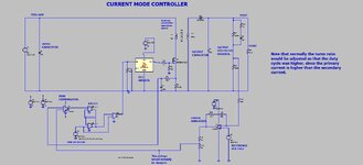
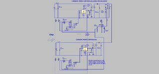
Is there a really basic 2 phase ( or 3 phase ) boost control IC out there with low side gate drive ? 0 - ~90% duty cycle on each output ( overlapping as it is boost 2 phase ) - ideally curr mode - but not fussy - any solution that only goes to 49% D on each o/p is no good.
 
Dont know if these are basic enough...


--- Updated ---

Though yes....otherwise Good old UCC28C43 with two of them sync'd by an anti-phase pair of synch signals, sounds like the most basic way.
--- Updated ---

Or what about two MCP1630's, which are easy to sync up...
--- Updated ---

Multi phase boost is being done a lot in the auto sector at the moment, getting a 48V rail from a 12V battery rail...but they all seem to be doing it with microcontrollers or FPGA's to do the control.
 
Last edited:
Yes well, its pretty amazing that the type of controller required in the top post does not really exist.
Specially when you think that the attached is all the circuitry that is needed to do a "current mode controller".
(LTspice and jpeg).

I mean, all that would be needed is to dump the attached on a chip, with 2 interleaving gate drives, and thats it....done....but such development has never happened, and we all know the reason for it......the Western Middle Men have crushed the Western SMPS industry, in favour of their imported SMPS's. -Imported from a place who are now publicly (even admitting it openly) stocking up the arms pile of those terrorists who recently rained down with over 100 (eg Shahed) drones.
 

Attachments

  • Current mode controller_parts.jpg
    Current mode controller_parts.jpg
    193.4 KB · Views: 46
  • Current mode controller _parts.zip
    2.4 KB · Views: 57
Last edited:
Hi,
Anyway, case you didnt have time or inclination, ive done you a nice Dual interleaved current mode controller.
As attached in LTspice and jpeg.
(ive done in in Flyback here but ayk, could be boost.
Not sure how difficult it would be for a semico to make this.
Its just basically a UCC28C43 with Two oscillators, phase shifted, and two gate drives, and two current sense comparators.

The attached, aswell as being so simple, (and solving OPs problem) seems like a damned good idea.....eg for those boosters where you'd need a heatsink on diode/fet for a single boost, but not for a dual boost...and being interleaved, the ripple is higher frequency.

Our middle men get stinking just doing it as single booster with heatsinks and importing it in.....thats why this wont ever happen.
 

Attachments

  • Current mode controller_DUAL INTERLEAVED_parts.jpg
    Current mode controller_DUAL INTERLEAVED_parts.jpg
    174.3 KB · Views: 44
  • Current mode controller _DUAL INTERLEAVED_parts.zip
    3.6 KB · Views: 57
Last edited:
Hello Dick, we have a business plan, and we have a fair bit of hardware, engineering is optimising for cost / performance trade off

We are looking at a small uP to perform the functions, but are open minded about an ASIC if there is a good one to buy

the LM5032 comes close, we have a discrete design for fully CrCM ( BCM ) too, using 2 x 555 ic's and an opamp - which performs very well and has 2 distinct advantages: 1) very good dynamic performance ( as not CCM ) and 2) much lower RFI as the turn on is zero loss ( ZVS )

thank you for your comment though.
 
I think this is a nice design for 500 W but costly for 10W.

This was just an example of some improvements. But ultimately you ought to have Design Specs 1st, simulation 2nd. then cost reduce, enhance performance. This is still just <1% of the effort needed to commercialize.

1703990173412.png
 
Last edited:
0 - ~90% duty cycle on each output ( overlapping as it is boost 2 phase ) - ideally curr mode - but not fussy - any solution that only goes to 49% D on each o/p is no good.

Method using separate counters for each converter. This allows a single adjustment to vary duty cycle from a few percent to almost constant on, applying simultaneously to all converters.

This simulation has 4 bit counters although any desired amount is suitable. Halfway through a cycle the MSB changes state from low to high. This is used to turn on a second converter and start its own counter. DAC's compare each converter's output to user-selectable master threshold voltage. Each switching device turns its converter off independently of what phase the other converter is at in its cycle.

Every other method I've tried (I contrived many different setups) is limited to a certain range of duty cycle, either 1-50, or 50-99 percent.

Below shows how I set a variable threshold voltage hi or low (at righthand), to first provide a short interleaved duty cycle, then halfway through the run, selected a long interleaved duty cycle.

dual interleaved method w 4-bit counter DAC for each controller.png


Link to run above schematic in Falstad's animated simulator:


Choose Toggle full screen (under File Menu).
Enlarge scope traces by dragging upward on border of scope region.
 
U
Method using separate counters for each converter. This allows a single adjustment to vary duty cycle from a few percent to almost constant on, applying simultaneously to all converters.

This simulation has 4 bit counters although any desired amount is suitable. Halfway through a cycle the MSB changes state from low to high. This is used to turn on a second converter and start its own counter. DAC's compare each converter's output to user-selectable master threshold voltage. Each switching device turns its converter off independently of what phase the other converter is at in its cycle.

Every other method I've tried (I contrived many different setups) is limited to a certain range of duty cycle, either 1-50, or 50-99 percent.

Below shows how I set a variable threshold voltage hi or low (at righthand), to first provide a short interleaved duty cycle, then halfway through the run, selected a long interleaved duty cycle.

View attachment 187425

Link to run above schematic in Falstad's animated simulator:


Choose Toggle full screen (under File Menu).
Enlarge scope traces by dragging upward on border of scope region.
Logic gates make great high speed analog comparators as long as one recognizes the reality of logic threshold tolerances. This could be done with a FPGA and might be digital QPSK en/decoders with up/down counters.
 
For a while I tried to use other devices in Falstad's simulator (such as Schmitt triggers, op amps, SR flip-flops made from NAND gates, inverted inputs and non-inverted inputs, etc.). However at start-up these devices hadn't receive definite inputs from earlier devices. The output devices adopted indefinite states and did not function properly until I went through contortions re-arranging wiring to feed them definite signals, then re-arranging it back again to obtain sensible operation.

To make 3 interleaved is a further challenge, needing further effort to divide cycles by 3.
 
So how many phases are people interested in?

I've seen 2 and 3 mentioned. I've gone as high as teens in charge
pumps.

At some point I think it becomes sensible to just make a single,
and have the controller do the phasing. Or, perhaps some
intermediary, SSI-MSI logic that could produce 2-N phases
by pin-strap select, provide the xN and baseband clock-field and
so on.

Thinking about what a "digital power fruit basket" might look
like, as a family of purpose-aligned piece parts.
 
We normally design hi freq converters in the 1kW - 250kW range, mostly in the 100kW and above lately

This app requires a nominal 12VDC in ( 9.5 - 20V ) and 0 -> 30V out, with high dynamic performance for load variation - input variation.

hence CrCM Sepic ( max dynamic performance as not CCM ) also a tracking 0 -> (-) 30 Vout - hence another similar topology for that, both low RFI ( compared to any hard switched buck derived solution )

Size is an issue, as is cost for volume manufacture, as is time to market

our 2 x TLC555 + opamp looks to be the most optimised solution so far - does everything and can be made small & cheap & fully ZVS at turn on

( a uP with fast A/D would work well also )

Regards

EP
 

LaTeX Commands Quick-Menu:

Part and Inventory Search

Welcome to EDABoard.com

Sponsor

Back
Top