thannara123
Advanced Member level 5
While learing sinewave inverter ,
I found that
"Double-closed-loop PWM design and control method for single-phase inverter current inner loop and voltage outer loop. By establishing the mathematical model of the single-phase inverter, the current inner loop control can obtain rapid dynamic performance, and the voltage outer loop control can improve the steady-state performance of the system ".
for keepping the Invertere output to a steady state without variations , we use feedback , ie , The voltage feed to the PWM to controll the signal by the help of a PI control system.
as per the error voltage the the corressponding scaler factor + normal Duty cycle value will be effected .
But How the current loop works ,
In some of IEEE papers the volatge and the current connected back to back of each PI control system .
How the scaling factor works .?
I am asking basically the working of inverter which having Double Closed Loop Control Method of Single-Phase Inverter.
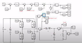
one of desgin got from internet as follows here feed the ILoad and Inverter Load
I found that
"Double-closed-loop PWM design and control method for single-phase inverter current inner loop and voltage outer loop. By establishing the mathematical model of the single-phase inverter, the current inner loop control can obtain rapid dynamic performance, and the voltage outer loop control can improve the steady-state performance of the system ".
for keepping the Invertere output to a steady state without variations , we use feedback , ie , The voltage feed to the PWM to controll the signal by the help of a PI control system.
as per the error voltage the the corressponding scaler factor + normal Duty cycle value will be effected .
But How the current loop works ,
In some of IEEE papers the volatge and the current connected back to back of each PI control system .
How the scaling factor works .?
I am asking basically the working of inverter which having Double Closed Loop Control Method of Single-Phase Inverter.
one of desgin got from internet as follows here feed the ILoad and Inverter Load