Aswinth Raj
Newbie level 4
- Joined
- Dec 8, 2014
- Messages
- 7
- Helped
- 0
- Reputation
- 0
- Reaction score
- 0
- Trophy points
- 1
- Location
- coimbatore,tamil nadu,india
- Activity points
- 64
Hi,
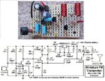
I have been trying to build a simple FM transmitter as a hobby project and used a circuit that I found online. The circuit is given below
![FPRK3CDHXRU3W14.MEDIUM[1].jpg](https://www.edaboard.com/data/attachments/45/45510-1cb1d202c9cc57c62326d7a19b7a2e31.jpg "FPRK3CDHXRU3W14.MEDIUM[1].jpg")
I know the circuit is working since someone has made it and documented it with a POC video here
https://circuitdigest.com/electronic-circuits/how-to-build-fm-transmitter-circuit
My question is how is such a simple circuit built on a breadboard works? I tried the same circuit and it is not working:bang:
I also tried everything suggested in this thread
https://www.edaboard.com/showthread.php?320858-fm-transmitter-circuit-not-working
Initially I started building this circuit on breadboard but many people say that Oscillatory circuits should not be built on breadboard so should I move to a pref board?
Also is it not okay to use a simple wire as antenna? Some people suggest for a yogi antenna? I am totally confused now:!: please guide me
Thanks
I have been trying to build a simple FM transmitter as a hobby project and used a circuit that I found online. The circuit is given below
I know the circuit is working since someone has made it and documented it with a POC video here
https://circuitdigest.com/electronic-circuits/how-to-build-fm-transmitter-circuit
My question is how is such a simple circuit built on a breadboard works? I tried the same circuit and it is not working:bang:
I also tried everything suggested in this thread
https://www.edaboard.com/showthread.php?320858-fm-transmitter-circuit-not-working
Initially I started building this circuit on breadboard but many people say that Oscillatory circuits should not be built on breadboard so should I move to a pref board?
Also is it not okay to use a simple wire as antenna? Some people suggest for a yogi antenna? I am totally confused now:!: please guide me
Thanks