Vermes
Advanced Member level 4
Hardware:
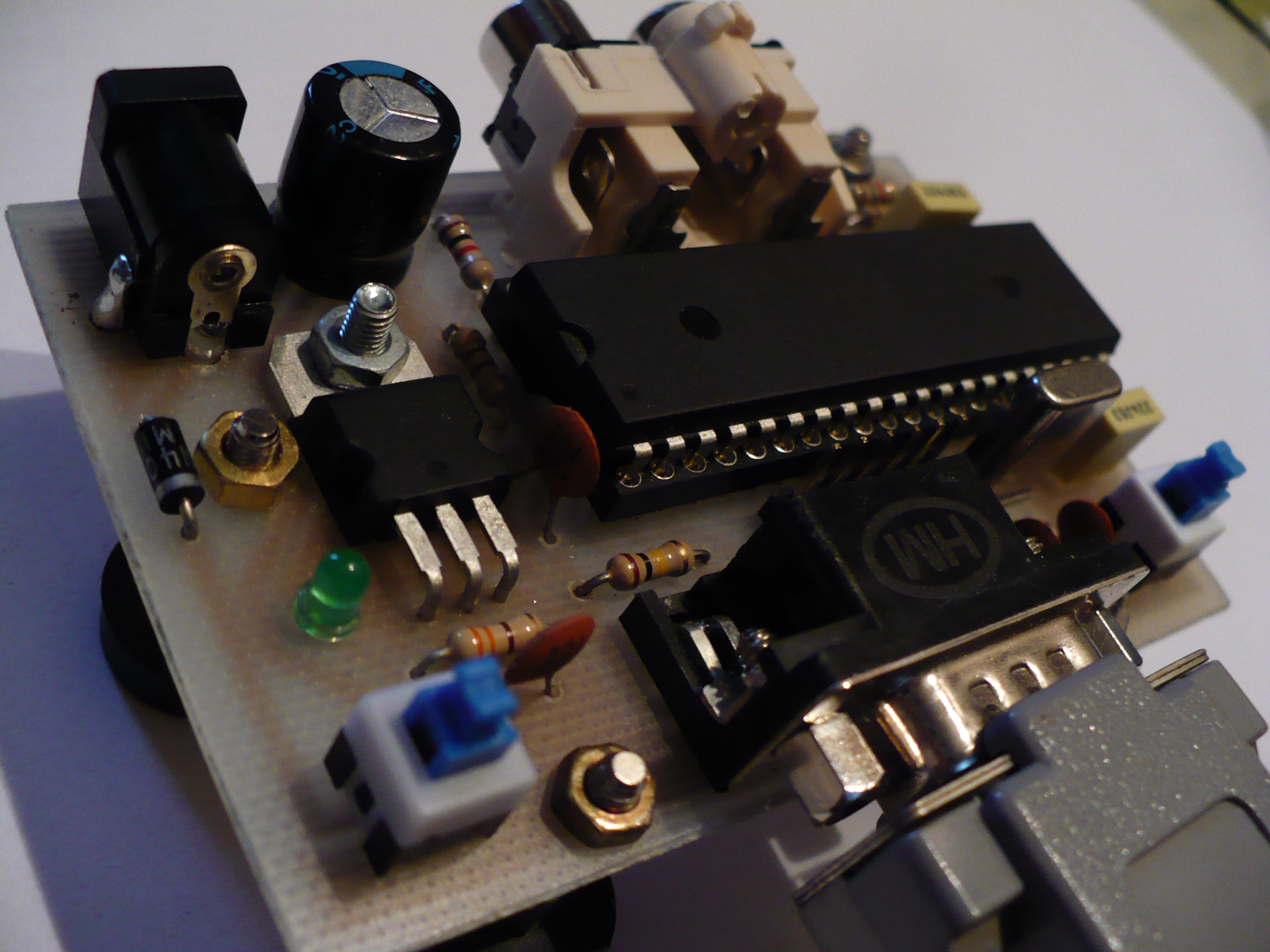
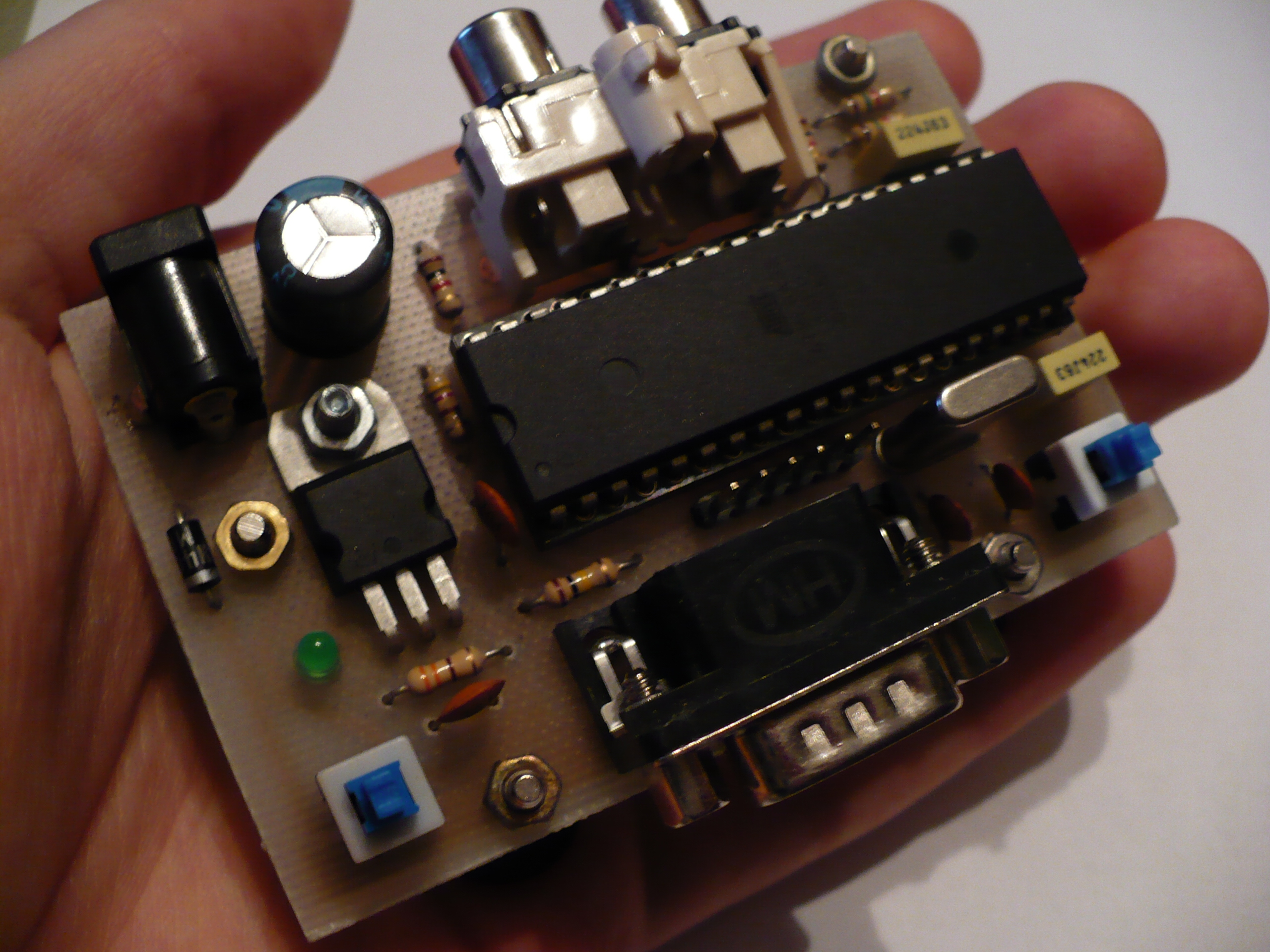
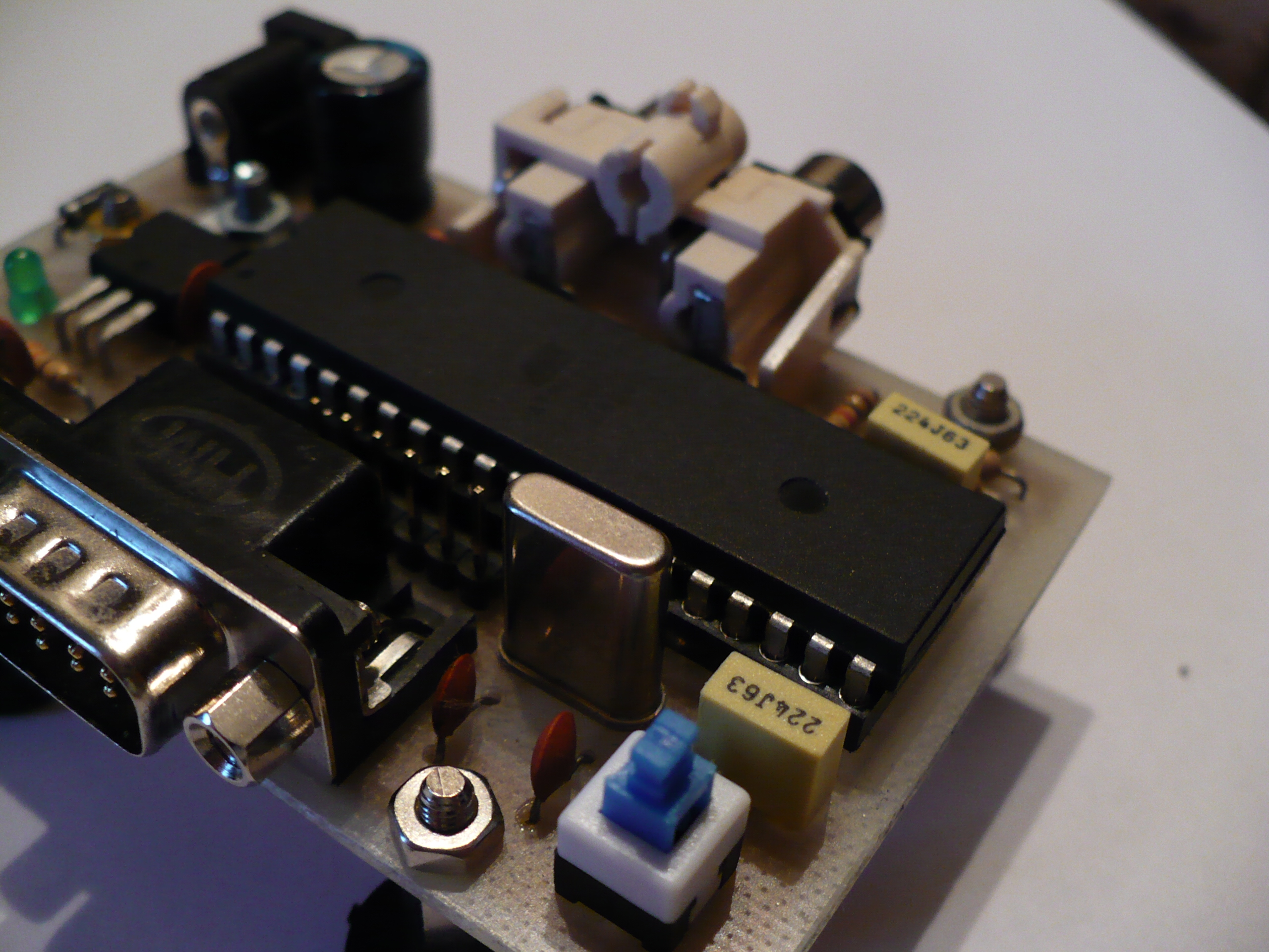
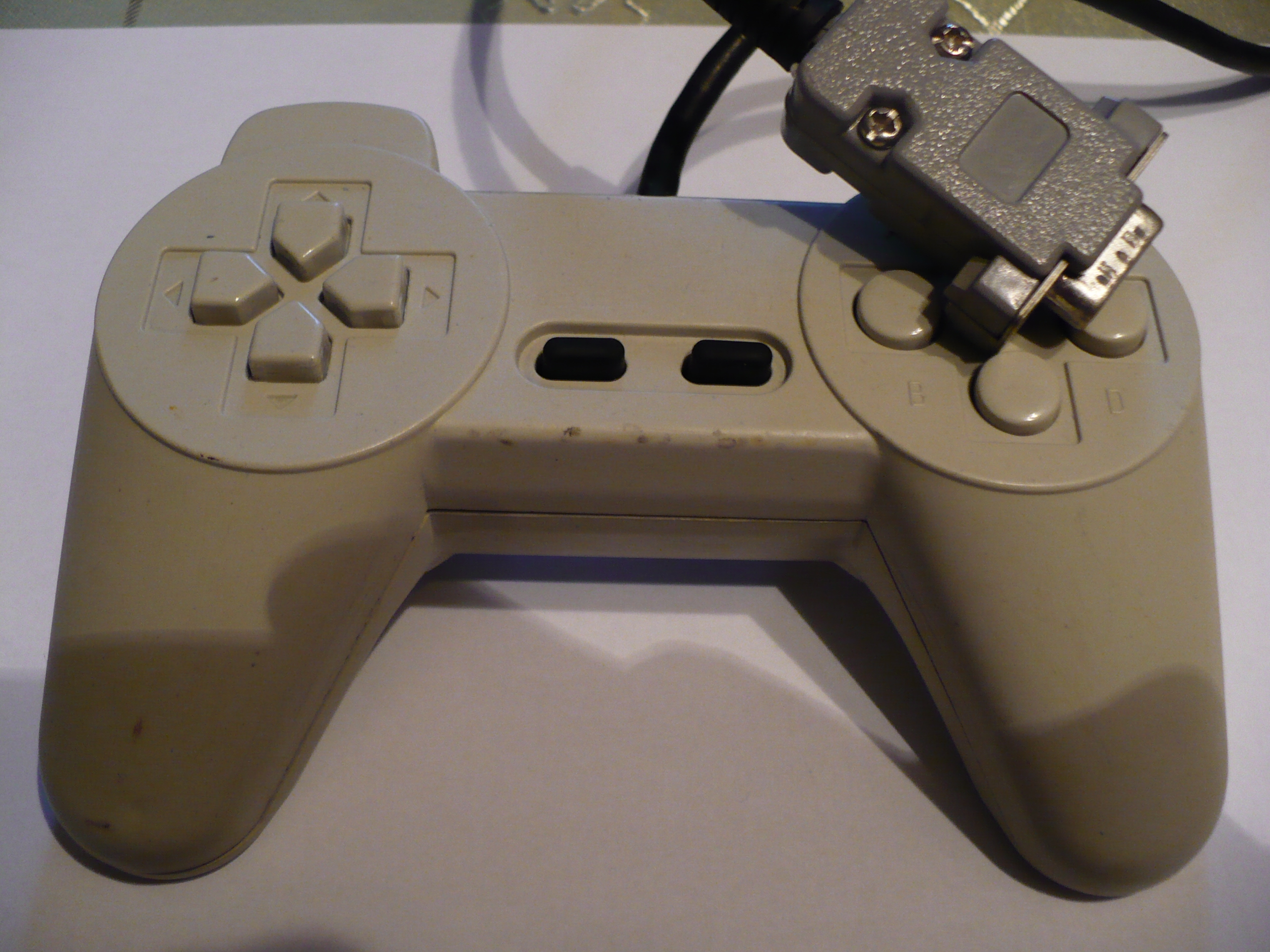
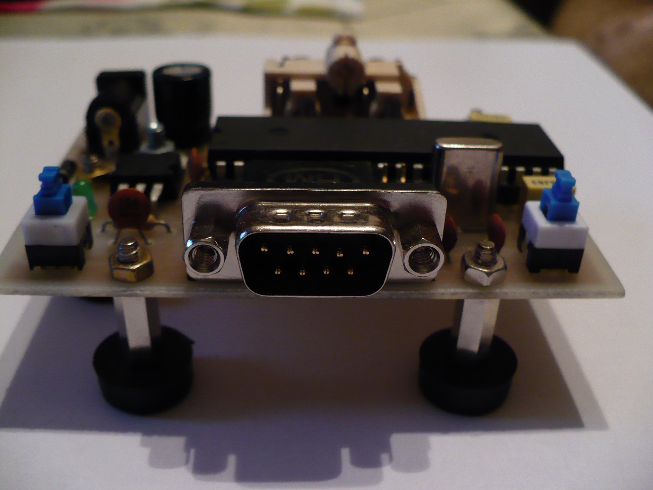
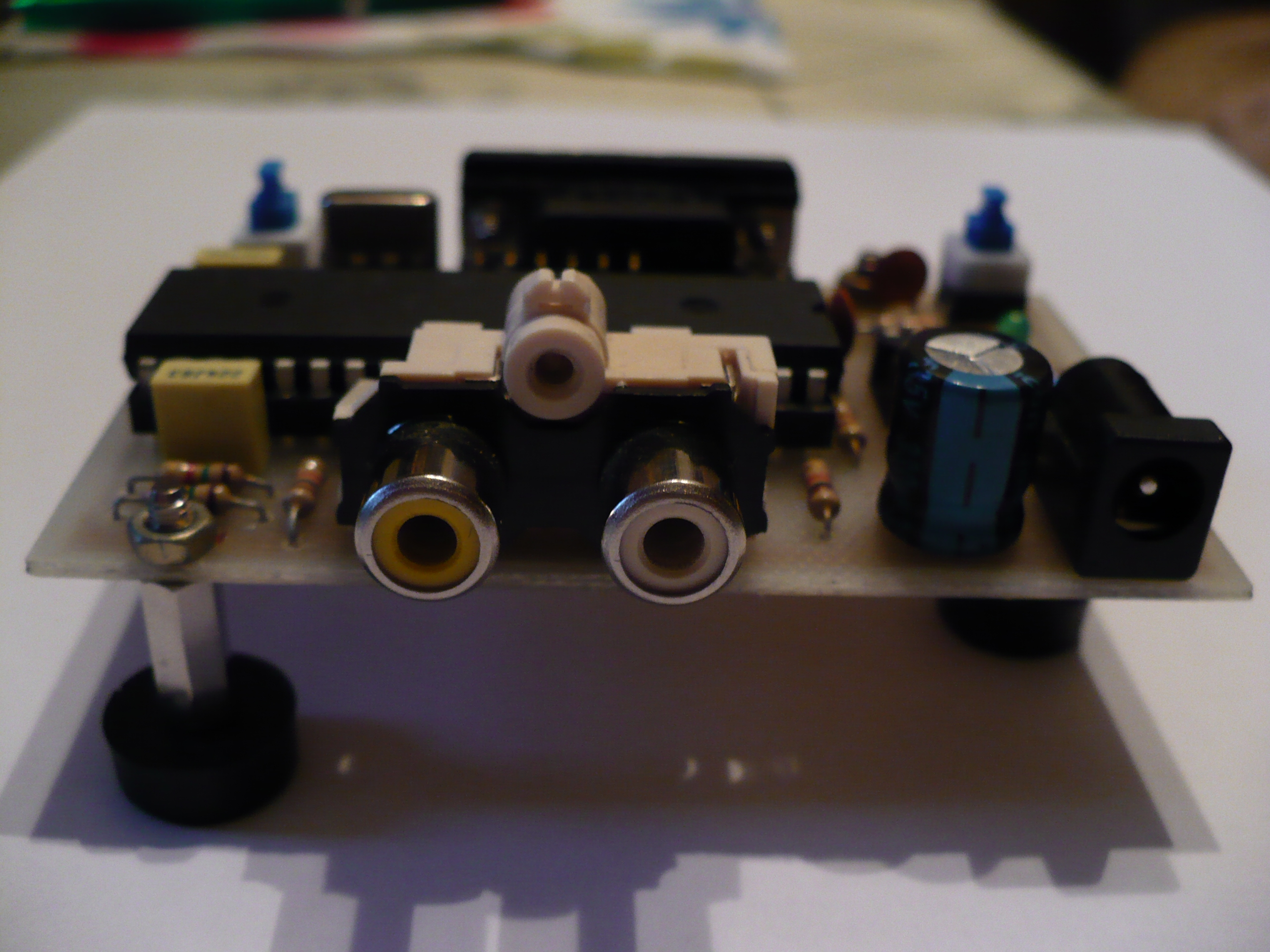
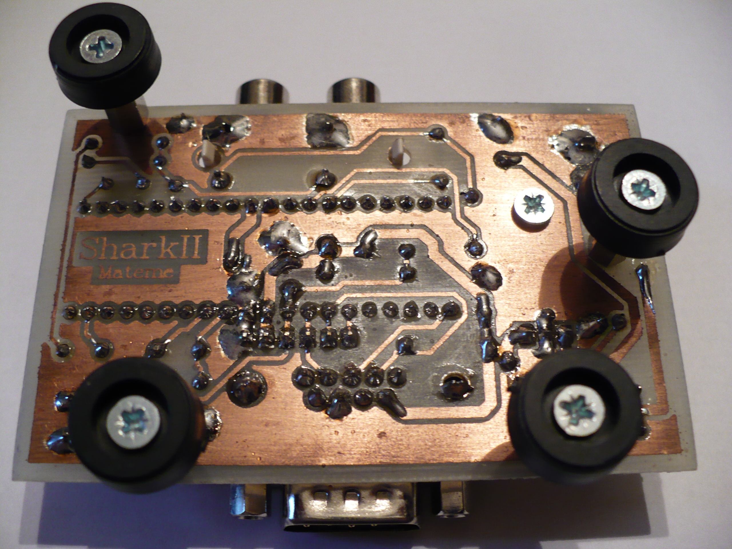
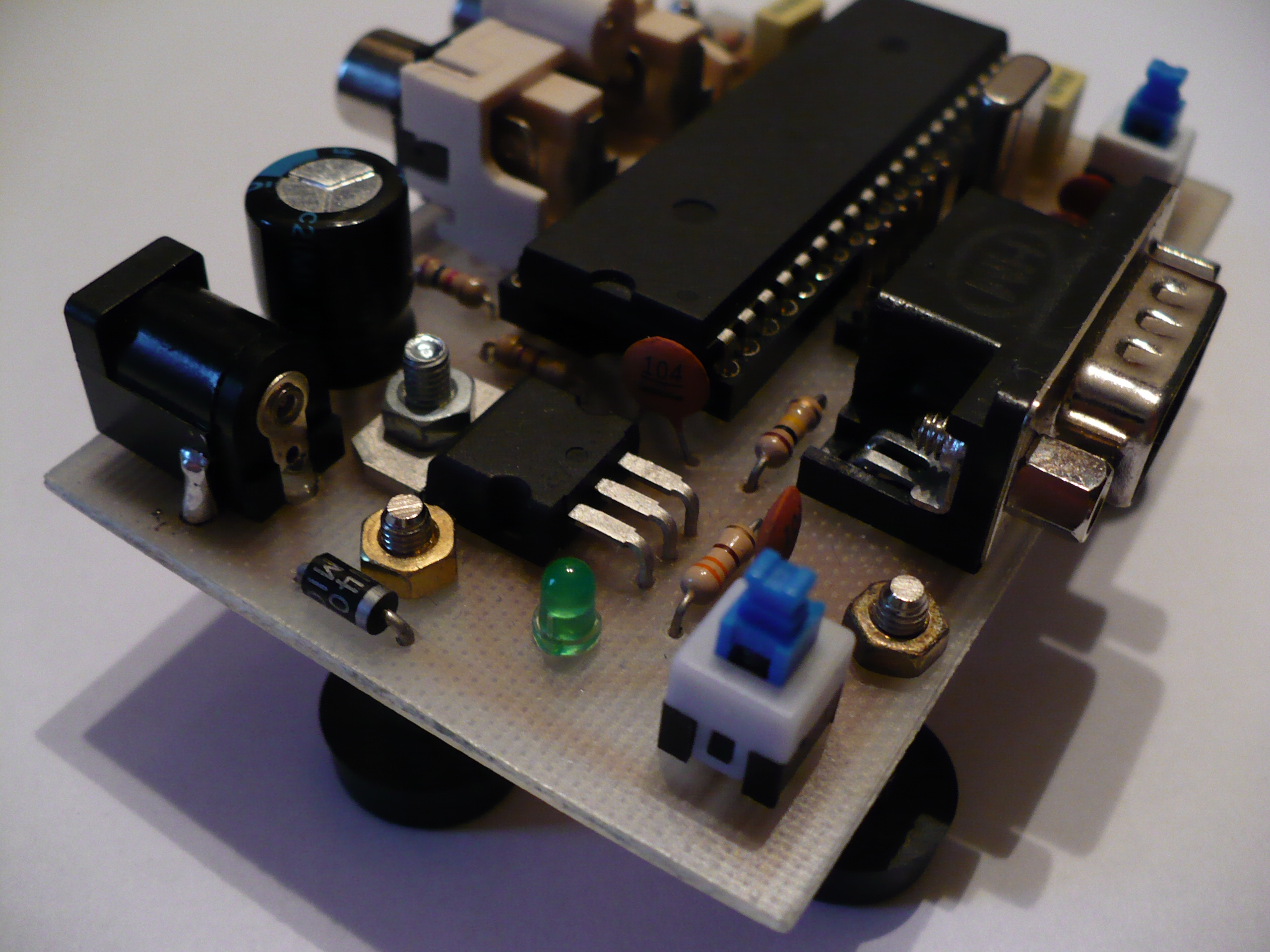
It is made on an universal board with 40 pins stand, with AVR plugged. Atmega32 in this device operates at a frequency of 16MHz, the maximum that is guaranteed by the producer. Composite image is generated using a simple D/A converter, consisting of two resistors, which runs through the impedance of the video input. Thanks to this simple converter, it is possible to get three colours: white, grey and black plus the level of synchronization signal. Internal PWM generators were used for the generation of sound. Using resistors, the signal level was respectively matched to achieve the level no greater than -10dBV, which is a standard in RTV devices. Of course, the signal value is not critical and could be less – the user can precisely set the volume in the TV according to individual preferences. Additional capacitors separate the constant component. The device provides two audio channels, but now it uses only one (OC1A output). The whole is powered by the system 7805. The system does not require a heat sink. Additionally it was screwed to the board in order to achieve better mounting. Some ceramic capacitors ensure proper filtering of the supply voltage. Also a diode that protects against reverse polarity of supply voltage was used. Data line from the pad was for security tucked by the resistor to the positive. Only hole elements were used. There are two buttons in the console: the one under the diode attaches the entire system and the one on the right is used to reset the device.
The program:
The software was written in WinAVR. The control program is a mixture of Assembler and C. The whole procedure of displaying is based on a large table, which content reflects the TV screen. In the meantime of the image support, the processor deals with the pad support and sound generation. There are 50 readings of the buttons state within a second and making them available to the procedures in the games. Additionally, using two 8-bit variables, simple virtual timers that count down the time were implemented. During the vertical synchronization, their contents are always increased, and accordingly by deleting them and checking their status, the main procedures are able to perform some actions in more or less regular intervals. A special software SkarkI3mageConverter (package of Dev C++) was written for works on the console. It was used to process the graphic into a form which is understandable to the procedures for viewing and easy conversion to three shades of grey. Any results obtained in the game are stored in internal EEPROM. The whole code is approximately 29kB, the most of which is graphics.
Games:
There are four games, the selection of which can be obtained via a simple menu after starting the console. After selecting the game, it will be run until the reset or re-enable the device.
- Crilux – the action takes place in a distant galaxy, the player is a spaceship pilot. Your task is to circumvent the asteroids that suddenly appear. But the escape would be too simple, therefore, the ship is equipped with a cannon, which allows for shooting down the flying asteroids.
- Snake – it is a classical game, which saves three best results. You have 4 levels of speed to choice. The principle is simple, the higher level, the more points. Exactly at level 1 you have one point for the snake food, at level 2 you have two points etc. The game ends when we do harm to our snake by ordering it to bite itself.
- Memory – ideal for lovers of memory training. The game begins with 40 randomly arranged cards displayed. Your task is to find pairs. After selecting two cards, they are uncovered for a short time. If they are the same, they disappear from the board, otherwise they shall be covered and the game goes on. The game ends when all pairs are found. The game counts the number of steps in which you find all the pairs and the time that was needed to do that. Best results are saved.
- Tetris – you should arrange the following parts to fill the whole lines. The full lines are removed with the legendary sound. It is also possible to accelerate the falling part by pressing the down arrow. The current score is displayed, then the next block and the number of filled lines. Number of points scored is the square of the number of lines simultaneously cleared, i.e. at 3 lines, you have 9 points, and at 4 – 16. The game ends when the next falling part does not have a possibility to move. Of course, the best results are saved just like in the other games.
- Video output: composite signal, RCA
- Audio output: RCA
- Resolution: 96x72
- Number of colours: 3 (black, grey, white)
- Supply voltage: 7,5V – 25V DC
- Current consumption: 40mA max
- Signal compatibility with the original NES pad: yes
The console has a hidden configuration menu. In order to activate it, simultaneously press and hold the SELECT and START buttons after you start the console and during displaying the startup logo, until the menu appears. It is possible to enable and disable sounds, set the standards results. You can also cancel all the results in all games. Completion of the operation is indicated by the sound, of course, if the sound is enabled. The last option is the information about the author.
Installation and start:
The application of a stand below the microcontroler is necessary, because of that few elements can be placed inside it. Please also check the inside of the stand if nothing interferes. Firstly mount the elements inside the stand and remember about the jumper, which is there. After assembling the whole and before loading the CPU to the stand, check with the measure whether on the relevant outputs there is the voltage of about +5V. After the run, you have to upload the feed to the EEPROM. To do that, enter the configuration menu and choose the “Default scores” option. After a while you have respectively stored memory.

Link to original thread (useful attachment) – SharkII, czyli prosta konsola oparta o mikrokontroler