Continue to Site

Welcome to EDAboard.com

Welcome to our site! EDAboard.com is an international Electronics Discussion Forum focused on EDA software, circuits, schematics, books, theory, papers, asic, pld, 8051, DSP, Network, RF, Analog Design, PCB, Service Manuals... and a whole lot more! To participate you need to register. Registration is free. Click here to register now.

RUBY AMP CIRCUIT (not turning on)

Status
Not open for further replies.
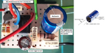
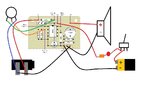
Yes, your photo shows the output capacitor connected backwards that might have destroyed it, the speaker and the LM386.
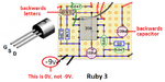
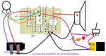
Your new parts layout shows the Jfet transistor correctly turned around but now its GSD letters are backwards.
The volume control should not crackle when it is turned because it should have no DC in it. Do you have a voltmeter? The volume control is supposed to be a Log type, not a Linear type.

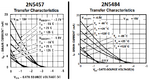
The Jfet transistor has an extremely high input impedance like an old vacuum tube. All old electric guitars used vacuum tube amplifiers and today some still do. But the input impedance of the LM386 with a 10k volume control is 181 times less and would cause an electric guitar to have a low output level with all the mid and high frequencies missing.
 

Attachments

  • Ruby amp again.png
    Ruby amp again.png
    1.3 MB · Views: 158

Oh. About the volume. The crackle is there but the volume pot works smoothly and the crackle and noises go down. I don't understand. If the chip and the speaker got destroyed, why is it that I got guitar signal when I pressed with my finger the part circled in previous posts? nothing smells like burned or nothing like that. I didn't see the letters on the transistor, but the person who drew it may go it wrong, aswell as the capacitors. I know that the draw of the capacitor is the other way around, but the "+" looks right. the 220uF cap has the "+" connected to the + of the speaker. if I put the capacitor like in the drawing, it would be the negative of the cap to the positive of the speaker, right? thats why I put them the other way around.
 

Your amplifier works when you press on it because a connection is bad or missing,

You are confused because the speaker is wrongly marked + and - instead of A and B.
The speaker is a small coil of wire with one end connected to ground (0VDC) and the other end is driven with AC (with no DC) from the capacitor.
The output pin of the LM386 amplifier is at half the positive DC power supply voltage so that audio can swing it up and down. The capacitor blocks the DC but passes the AC audio.
Therefore the + wire of the capacitor connects to the LM386 and the - wire of the capacitor connects to the speaker.
 
To avoid any doubt here is the pin order on that transistor
Screenshot_20201106_085217.png

According to the data sheet, it is a symetrical FET, that means the source (S) and drain (D) pins are interchangeable but the gate certainly isn't.

I didn't mean to permanently remove the transistor stage, just to isolate the problem by injecting the signal after it instead of before it. As it doesn't provide any amplification, the volume should be about the same.

Brian.
 
Your amplifier works when you press on it because a connection is bad or missing,

You are confused because the speaker is wrongly marked + and - instead of A and B.
The speaker is a small coil of wire with one end connected to ground (0VDC) and the other end is driven with AC (with no DC) from the capacitor.
The output pin of the LM386 amplifier is at half the positive DC power supply voltage so that audio can swing it up and down. The capacitor blocks the DC but passes the AC audio.
Therefore the + wire of the capacitor connects to the LM386 and the - wire of the capacitor connects to the speaker.

Ok, so in retrospective the Transistor and the polarized capacitors are backwards? Still, what I don't understand is why I managed to get guitar signal (pressing the part of the board with my finger) ? it shouldn't make any sound if this components are bakcwards, right? or am I wrong?

Thank you.
--- Updated ---

To avoid any doubt here is the pin order on that transistor
View attachment 165432
According to the data sheet, it is a symetrical FET, that means the source (S) and drain (D) pins are interchangeable but the gate certainly isn't.

I didn't mean to permanently remove the transistor stage, just to isolate the problem by injecting the signal after it instead of before it. As it doesn't provide any amplification, the volume should be about the same.

Brian.
Ok, so, as I told Audioguru, the transistor and polarized capacitors are backwards. If so, why I managed to get sound from it? shouldn't it be complettly silent? or blown up or something? haha.
--- Updated ---

I just took a reading of the speaker with a multimeter to see if it got destroyed and it shows a 10 ohm reading. If its blown it should show infinite ohms as far as I know.
 
Last edited:

I found this picture of a Ruby amp and you are correct about the capacitors, but only one of them seems to be backwards, the other one is in its correct position. Well, I should try that and see what happens.

1604680982635.png
 

I also posted the correct photo from Run off Groove.
I said that only your output capacitor and Jfet are backwards. Your 100uF capacitor polarity is correct.
I said that only the letters on your turned around Jfet are backwards.

A backwards capacitor can work for a short time then explode or become shorted.
Your circuit can work when you press in it if pressing bypasses the backwards Jfet or disconnect it from messing up the signal.

A speaker should never have DC in it from a backwards coupling capacitor. DC might cook the enamel on its coil and cause it to get stuck but still show the correct ohms.
 

Attachments

  • ruby on and on.png
    ruby on and on.png
    48.2 KB · Views: 155

I flipped the draw of the transistor but forgot to flip the letters, so it must be OK. I flipped the 220 capacitor but still, have the same problem. I guess I'll have to do it again and practice. Thank you.
--- Updated ---

What happens if I use another kind of transistor? I have a 2N5484. I have another transistors that I've got from an old 80s telephone but they are other models.
--- Updated ---

What happens if I use another kind of transistor? I have a 2N5484. I have another transistors that I've got from an old 80s telephone but they are other models.
--- Updated ---

I noticed difference between the diagram and the real picture of the components. the resistors are in different positions so I don't know wich one is correct!
1604691433021.png
1604691443004.png

--- Updated ---

Nevermind, I see that the connections are right just moved one hole up but still connected correctly. I'll build this one.

1604691656909.png
 
Last edited:

Compare the spec's for the Jfet transistors so see if a 2N5484 has a different IDss then needs to have the 3.9k source resistor value changed.
The wiring at Run Off Groove is a mess and the important 10 ohms resistor is missing. It is in EVERY schematic in the LM386 datasheet.
but they used a Japanese 386 amplifier that might be different.
 

I know the the picture is a mess and its missing the resistor, but I followed the detailed drawing. Here is the wiring I've done. This wiring is a bit different in terms of how the volume pot is wired. The 1st lug is going to the "sleeve" of the guitar jack. When I turn it on, the LED comes up, there is background noise, very little, but when I touch the volume pot it starts to do fast clicking sounds "TAC TAC TAC TAC"

I've found a website that tells you what other transistor you can use as a replacement of the 2N5457 and the 2N5484 is NOT one of them, so maybe thats the root of the problem. In the previous built I put the 2N5457 but as I was taking it off the pcb to put it in the new one the middle leg broke off. I'll have to buy another.
 

Attachments

  • Ruby with LED.png
    Ruby with LED.png
    27.8 KB · Views: 261

Jfet transistors have a wide range of IDss of five to one. The 2N5457 and 2N5484 have parts of their spec's that are identical but in this simple circuit some will work fine and others will work poorly.

Today's pots wiring is the same as before.
 

Attachments

  • Jet comparison.png
    Jet comparison.png
    75.8 KB · Views: 145
  • ruby pots.png
    ruby pots.png
    21.3 KB · Views: 144

I'm in late on this discussion so I might have missed.
I notice the input on your schem, and on the pic above the input goes straight to the fet, does your guitar have any active circuitry, ie anything battery powered?, if theres any Dc in the input to the ruby it might saturate the input fet.
You could temporarily try a 0.1 in series with the input.
Usually you calc the drain resistor of the fet to drop around 2 volts with Idss flowing through it, or just scale the drain resistor, a fet with twice the Idss half the resistance.
Tac tac tac sounds like motorboating, is the battery Ok?, and the resistor/cap on pin 5 of the '386?
I think betwixt mentioned this, as a test you can remove the fet and apply the input to what was its drain connection, if you get sound its the fet circuit, if you dont its the chip.
 

I agree that maybe the battery is dead. it would need a miracle for it to survive the 53 posts in this thread.
What is the battery voltage when it is connected to the circuit?
What is the DC voltage at the source (S, middle) pin of the Jfet?
 

I replaced the transistor for a 2N5457, and when I connect the guitar and play it, the only sound the amp mades its a TAC TAC TAC TAC, just when I play the guitar. I am very much confused about some parts not knowing where to solder them in the board. it is not in the picture.

This is the wiring I've done. I'm not sure about the grounding part of the board, I put together the - of the battery, the - of the speaker and the - of the jack. Also, not sure about the 3rd lug of the volume pot going to the - of the jack aswell. The Battery is new.

Again, sorry if I'm saying something wrong or obvious, but its confusing. Each time you look for some information on how to do it, something is backwards, not in its place, etc. I'm trying to figure how to read the schemantics but its taking me forever, I need to build this amp.

Thanks.
 

Attachments

  • RUBY problem.jpg
    RUBY problem.jpg
    113.8 KB · Views: 134
Last edited:

I see a couple of mistakes on your drawing.
The wires to the jack are the wrong way around.
And you have power going through the led, + should go to the led and the board, and the resistor side of the led should go to ground, this is most likely the cause of the tic toc tac.
The ground connections you've shown look correct.


Sorry, the jack is correct, I forgot to indicate that the little square on the right of the jack is the tip, not the nut and washer. Yes, I now realize that I put the LED wrong. I took it out and the amp works! now I have to put the LED correctly ! Thank you!
 
Last edited:

Now you have the entire amplifier powered from the low voltage and low current from the LED instead of directly from the from the battery and its switch.
You said earlier that you have a voltmeter. Then please use it to measure and report to us:
1) The battery voltage when it powers the amplifier and brightly lights the LED with its series resistor.
2) The S pin of the Jfet.
3) The output pin 5 of the LM386 when it has no sounds.

Of course the ground pin of the volume control must connect to ground. If it doesn't then the volume would be at full blast all the time.
 

Attachments

  • ruby amplifier corrections.png
    ruby amplifier corrections.png
    268.6 KB · Views: 182
Now you have the entire amplifier powered from the low voltage and low current from the LED instead of directly from the from the battery and its switch.
You said earlier that you have a voltmeter. Then please use it to measure and report to us:
1) The battery voltage when it powers the amplifier and brightly lights the LED with its series resistor.
2) The S pin of the Jfet.
3) The output pin 5 of the LM386 when it has no sounds.

Of course the ground pin of the volume control must connect to ground. If it doesn't then the volume would be at full blast all the time.
All set and working propperly! Thank you everybody for your help! I will keep practicing!
 

Well done.
If you link the unused pins of the jack it'll be quiet when nothings plugged in.
I have an effects pedal somewhere that uses '386's, handy little chip.
 
Status
Not open for further replies.

Part and Inventory Search

Welcome to EDABoard.com

Sponsor

Back
Top