Continue to Site

Welcome to EDAboard.com

Welcome to our site! EDAboard.com is an international Electronics Discussion Forum focused on EDA software, circuits, schematics, books, theory, papers, asic, pld, 8051, DSP, Network, RF, Analog Design, PCB, Service Manuals... and a whole lot more! To participate you need to register. Registration is free. Click here to register now.

RUBY AMP CIRCUIT (not turning on)

Status
Not open for further replies.
The backwards LED problem is simple but it has nothing to do with why the amplifier does not work.
An LED is a diode. It conducts current only when its anode wire is positive and its cathode wire is negative. Most 5mm size LEDs are very bright at 20mA but over 30mA will burn them out. With your 2.2V green LED and a 9V battery then a resistor value of 1.2k ohms will be bright and not use much battery power. Your resistor was 47 ohms which would have produced a current of (9V - 2.2V)/47 ohms= 145mA. The maximum allowed backwards voltage for an LED is 5V so yours might have been destroyed by 9V.
 
I wouldn't worry too much, the value in the text is 4.7K which is correct. The color bars in the picture are ambiguous, most resistors do not use four bars and if you use only the first three, as you normally would, it would indicate 47 Ohms which as Audioguru points out would probably damage the LED. However if all four bands are used it would indicate 4.70K which is fine but more accurate than it needs to be.

The LED will not stop the amplifier working, it is only to show when it is switched on.

Brian.
 

Some checks you can do:
Is there a pop at switch on or off?
Can you hear absolutely nothing from the speaker even with a signal applied?
Does the led vary its brightness with a signal applied?
You can connect the speaker to the battery briefly through a 1k resistor to check it, as you do so the speaker should rustle.
Some people connect the battery direct to the speaker, its a bit risky doing that.
If your using a lightweight switching type wallwart that could be making the '386 go unstable, this would make the resistor on pin 5 get warm.
 

Post #10 says the speaker produces a hum sound so the amplifier must be working.
Then the problem must be with the input plug or jack.
 

Hello!

Well, I couldn't manage to get it to work so I found another wiring and try that one (attached)

This time there is popping and crackeling but no sound what so ever. Every component is in its right place and the conections are just like in the picture. Maybe is because of my messy soldering job :ROFLMAO:
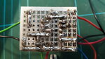
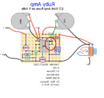
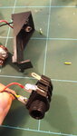
... The only doubt is in the conections between the resistors and the transistor and the guitar jack. I put a little wire from one tip of the resistor to its right place (1 and 2 holes of the pcb) but I see that the blue line does not have a point of conection to the legs of the transistor. I mean, if there is something wrongly conected, it shouldn't do any sounds, right? But there is a background sound, I turn the pots up and down and they seem to work OK, I touch the components and they make noise, but no sound from the guitar.

What do you guys think? I tried to retouch some of the points and components, but everything is correctly solder. Or maybe the wiring is wrong in the first place. I'll attach the wiring diagram from the top and fliped horizontaly so you can compare the soldering joints.
--- Updated ---

An update!

I push with my finger in the circled area and the guitar comes on, a bit weak, or it makes a loud high pitch noise. I guess I have to retouch that solder points
 

Attachments

  • 20201105_134111.jpg
    20201105_134111.jpg
    3.4 MB · Views: 89
  • RUBY (from bottom).png
    RUBY (from bottom).png
    76 KB · Views: 90
  • RUBY 2.png
    RUBY 2.png
    91.7 KB · Views: 91
  • 20201105_134218.jpg
    20201105_134218.jpg
    1.1 MB · Views: 95
  • RUBY (from bottom) 2.png
    RUBY (from bottom) 2.png
    76.1 KB · Views: 89
Last edited:

It might be the gain is to low to get much volume.
You can increase the gain of the '386 greatly, I think a cap across pins 1 & 8, its in the datasheet.
Get the thing to work reliably before trying that though.
 

There is a potential problem (apart from it being much harder to build using that construction method!) and I'm beginning to wonder if it might also be the original problem as well. The input jack SOCKET is shown as stereo - but if you use a stereo PLUG it will stop it working! You have to use a mono plug, one with just a body and tip but no ring around it. The diagram also has the ground and signal connections to the jack socket reversed. This could damage the transistor!

Looking at the three connections on the jack socket and the 'Ruby 2' picture so the socket is on the left - the leftmost (blue) connection should have the two black wires connected to it, the rightmost connection should have the red wire connected to it.

The reason for needing a mono plug is that the negative of the battery has to connect to the negative line on the board. It does this because the metal body of a mono plug will link the front (entry end) of the jack to the nearest contact in the socket and allow power to flow. If you use a stereo jack the nearest contact will go to the ring around the plug instead and no connection will be made.

Brian.
 

I think thats right, might be a good idea to do away with the jack socket power switch and use a toggle switch, and a mono jack socket.
There could be other problems if you start using effects & mixers etc.
If you plugged stereo 'phones into that jack one of the 'phones would probably fry.
 
There is a potential problem (apart from it being much harder to build using that construction method!) and I'm beginning to wonder if it might also be the original problem as well. The input jack SOCKET is shown as stereo - but if you use a stereo PLUG it will stop it working! You have to use a mono plug, one with just a body and tip but no ring around it. The diagram also has the ground and signal connections to the jack socket reversed. This could damage the transistor!

Looking at the three connections on the jack socket and the 'Ruby 2' picture so the socket is on the left - the leftmost (blue) connection should have the two black wires connected to it, the rightmost connection should have the red wire connected to it.

The reason for needing a mono plug is that the negative of the battery has to connect to the negative line on the board. It does this because the metal body of a mono plug will link the front (entry end) of the jack to the nearest contact in the socket and allow power to flow. If you use a stereo jack the nearest contact will go to the ring around the plug instead and no connection will be made.

Brian.

Hi Brian!

Yes, I'm using a mono plug guitar cable. I don't understand what you are saying about the reversed connection.

As far as I know, the inner lug of a jack is where the sleeve of the plug makes contact so, it would be negative. and the outer lug makes contact with the tip of the plug beeing the possitive. All I see is the two black wires (negative) connected to the inner lug (sleeve of the plug) and the possitive to the outer lug (the tip) the negative of the baterry is going to the other lug of the stereo jack that makes contact with the sleeve of the plug, si ut seems to be correct as far as I'm concern. Also, I made an update just now saying that the guitar sound comes up when I touched the area in the red circle, maybe is a bad connection.

Thank you!
--- Updated ---

I think thats right, might be a good idea to do away with the jack socket power switch and use a toggle switch, and a mono jack socket.
There could be other problems if you start using effects & mixers etc.
If you plugged stereo 'phones into that jack one of the 'phones would probably fry.

Oh, ok! I should try that then. Something like in the picture attached you say?
 

Attachments

  • RUBY (from bottom) 2.png
    RUBY (from bottom) 2.png
    76.1 KB · Views: 79
  • RUBY 3.png
    RUBY 3.png
    76.5 KB · Views: 82
Last edited:

Way better yes.
The jack symbol is a little confusing, on an actual jack the terminal nearer the threads is usually ground, yours is shown different.
Contacts on jack sockets can cause trouble, a switch is more reliable.
The input impedance of the amp is really high, you might get crisp packet effect when the guitar cable moves, even with musiflex.
 

I notice that the Mosfet transistor pins are connected backwards.
 

Attachments

  • Ruby amp.png
    Ruby amp.png
    404.2 KB · Views: 79
  • original ruby amp.png
    original ruby amp.png
    551.3 KB · Views: 87

I notice that the Mosfet transistor pins are connected backwards.
it didn't work.
--- Updated ---

OK. I flipped the transistor, change the jack and added an LED with its resistor. Didn't work,
 

Attachments

  • 20201105_170130.jpg
    20201105_170130.jpg
    1.2 MB · Views: 72
  • RUBY 3.png
    RUBY 3.png
    77.7 KB · Views: 76
Last edited:

I see that the polarity of your output capacitor is backwards.
The speaker does not produce a DC battery voltage, the output pin of the LM386 has a positive voltage at half the supply voltage.
The backwards capacitor might have destroyed it, the speaker and the LM386.
 

I see that the polarity of your output capacitor is backwards.
The speaker does not produce a DC battery voltage, the output pin of the LM386 has a positive voltage at half the supply voltage.
The backwards capacitor might have destroyed it, the speaker and the LM386.
mmmm... The capacitors are ok. The drawing shows them with the negative terminal (the white line draw in the capacitor) backwards, but shows where the positive is, so I've guided by that.

Before I turned the transistor like you said, I was guetting guitar signal but by pushing the part of the circuit with my finger, like something is not doing propper contact. So, if the capacitors are backwards, I couldn't get any sound of it, right?

I know the drawing shows the negative of the capacitors the other way around, but look at the possitive sings in the drawing.
 

Attachments

  • RUBY 3.png
    RUBY 3.png
    77.4 KB · Views: 130

So the led lights up with the power switch in the on position now then?
Does the speaker pop at turn on.
Electrolytics can short if put in circuit backwards, and the '386 would be able to provide enough current to ruin the speaker coupling cap.
Does anything get hot?
There could be a dry joint making it work when pressed, sometimes the dry joint can be misleading and be away from where you press.
(after you get it working you could put a wire link across the 2 pins of the jack socket that have nothing connected to them, this will short the input and stop the loud hum you'll probably get without).

This is another wiring that I found. The first one that I posted here I couldn't managed to get it to work, so I found out a new wiring diagram with the components in other places of the pcb. This one seems to work out, at least it turns on and there is noise and cracks. Audioguru told me that the transistor is backwards, so I change it and its not working, there is popping but no guitar sound when I press the part of the circuit that I mentioned before. So, I guess I'll flip the transistor again and try to re-touch the solder to see if I get something.
 

Lets go back to basics:

Remove the transistor completely, the amp will still work without it so 'divide and conquer' by eliminating it as the cause of the problem. If you then touch the connection between 'a6' on the board and the volume control you should hear a buzz. You might need to turn the control to maximum to hear it.

Presumably the LED you added is lighting up when you switch on, please confirm.

The black plastic jack socket is a mono one, it cannot be used to turn the power on because the switches on it (the metal contacts that bend back when you insert the plug) open up and would in fact turn the power off!

The stripe on electrolytic capacitors is always the negative side and that refers to the voltage applied to it and not the +/- symbol of other components attached to it. In the amplifier, the negative sides should be the -9V connection and the loudspeaker.


Brian.

If I remove the transistor, what would happen? what role does the transistor have in this circuit?

The LED lighst up, yes. The amp turns on without a problem even when I plug the guitar. There is popping and crakleing when I move the pots up and down, but no guitar signal. Before flipping the transistor, I pressed with my finger the part of the board and the guitar would appear. Now, when the transistor flipped, there is no guitar even if a press the part of the board.

The amp does not turn off when I plug the guitar, so the jack is ok to use.
 

The transistor is there to increase the input impedance of the amplifier. It doesn't make the sound any louder but some say that a guitar pickup sounds 'brighter' when feeding a high impedance.

If you remove it completely and connect the signal wire from the jack socket directly to 'a6' the amplifier should still work but the sound might be a little 'duller' than before. If that fixes it, the problem is with the transistor stage. What exact type did you use?

Brian.
ok, I preffer to use the transistor to improve the sound. I don't think the problem is the transistor, it should be the conection that I'm pressing. The transistor is a 2N5457
 

Status
Not open for further replies.

Part and Inventory Search

Welcome to EDABoard.com

Sponsor

Back
Top