Continue to Site

Welcome to EDAboard.com

Welcome to our site! EDAboard.com is an international Electronics Discussion Forum focused on EDA software, circuits, schematics, books, theory, papers, asic, pld, 8051, DSP, Network, RF, Analog Design, PCB, Service Manuals... and a whole lot more! To participate you need to register. Registration is free. Click here to register now.

Regenerative detector with separate local oscillator, is that possible?

Status
Not open for further replies.

neazoi

Advanced Member level 6
Joined
Jan 5, 2008
Messages
4,123
Helped
13
Reputation
26
Reaction score
15
Trophy points
1,318
Location
Greece
Activity points
36,955
hello, I have read the wikipedia article Regenerative circuit - Wikipedia, the free encyclopedia
I would like to focus on the paragraph:

A major improvement in stability and a small improvement in available gain is the use of a separate oscillator, which separates the oscillator and its frequency from the rest of the receiver, and also allows the regenerative detector to be set for maximum gain and selectivity - which is always in the non-oscillating condition.[6] A separate oscillator, sometimes called a BFO (Beat Frequency Oscillator) was known from the early days of radio, but was rarely used to improve the regenerative detector. When the regenerative detector is used in the self-oscillating mode, i.e. without a separate oscillator, it is known as an "autodyne".

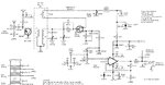
I try to think of this configuration as a means of avoid to have to set the regeneration each time I tune to a different frequency. I consider the attached regenerative RX.

I wonder, how this separate oscillator could be made? It has to have a means of feeding back in the input the MODULADED incoming signal in order to amplify it. Not just an unmodulated carier, this should be of no use.

Have you seen any of these separate oscillator regens anywhere?
 

Attachments

  • ggg.jpg
    ggg.jpg
    75.5 KB · Views: 117

unless you are running a museum and need to get some old vacuum tube equipment to work, I can not think of any reason you would use such a circuit today!
 

I think you have not built anything so far, and you thus fail to understand how a regenerative receiver works.

A regenerative receiver consists of a first stage with adjustable positive feedback, and an audio amplifier. The adjustable-feedback AM or CW detector can be adjusted either close to oscillation by feedback control- then AM signals are demodulated and the audio signal is amplified into earphone or a speaker.
If you adjust the feedback so the first stage oscillates, the audio output is the beat frequency between the oscillator RF frequency and the AM carrier, or a CW carrier. The oscillating regenerative detector thus operates as the BFO (beat-frequency oscillator) and you can hear RF CW signal- if carrying Morse-Code, you can hear dots and dashes.

From the above you can understand that an additional BFO is not needed in the regenerative receiver. You can obviously add the BFO and adjust the feedback so that the first stage does not oscillate; then the BFO will create a beat frequency with a RF signal. But by only adjusting the feedback to make the first stage to oscillate, you have the BFO in the first stage- so you need no more BFO to add.

Do experiment and learn of it! Talking is no way to experience!
 

I read the wikipedia article. Including the paragraph you quoted. Seems that regeneration is still on the scene.

The article lists short range applications such as "garage door openers, keyless locks, RFID readers, some cell phone receivers."

I once breadboarded an AM receiver, then added regeneration. Autodyne configuration (no additional oscillator).

I did get a huge gain in reception. But only after trying a lot of different adjustments. Coil positioning, etc.

Then suddenly things clicked. Just like magic the broadcast got louder.

Then I tuned to a different station. I had to do some adjusting again.

I had not heard of adding a BFO. It's worth some experimentation to see if makes for easier operation. And it's a step toward making a super-regenerative receiver. Achieving greater sensitivity with fewer components.
 

The superregenerative receiver (or detector) circuit is very different from a regenerative detector.
I described the second above.
The superregenerative detector is an oscillator interrupted by its own second feedback loop, or, by an external oscillator. The interruption frequency is often chosen to be above audio band. The detection principle consists in that when the RF oscillation starts after the interrupting pulse, the start begins either by noise (this is why the audio output typically is a strong noise), or, a RF signal from antenna. The varying RF signal (AM modulated) causes the oscillator output to be like a varying pulse width audio signal. Superregenerative detectors are sometimes used as the RF/audio gain is very high (1 million times) but the disadvantage is that they as oscillators radiate and interfere with other signals. To prevent such interference, a SR detector can be used after a RF preamplifier.

By a careful tuning on one side of a FM spectrum, a SR detector can demodulate NBFM but is not so good with a wideband FM.
SR detectors were popular when vacuum tubes and later RF transistors were expensive. Radio amateurs used them in simple receivers.
 

Status
Not open for further replies.

Part and Inventory Search

Welcome to EDABoard.com

Sponsor

Back
Top