Continue to Site

Welcome to EDAboard.com

Welcome to our site! EDAboard.com is an international Electronics Discussion Forum focused on EDA software, circuits, schematics, books, theory, papers, asic, pld, 8051, DSP, Network, RF, Analog Design, PCB, Service Manuals... and a whole lot more! To participate you need to register. Registration is free. Click here to register now.

Pulse Width Modulator Improvements

Status
Not open for further replies.

CrystalMan

Newbie level 5
Joined
Oct 24, 2013
Messages
9
Helped
0
Reputation
0
Reaction score
0
Trophy points
1
Activity points
56
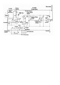
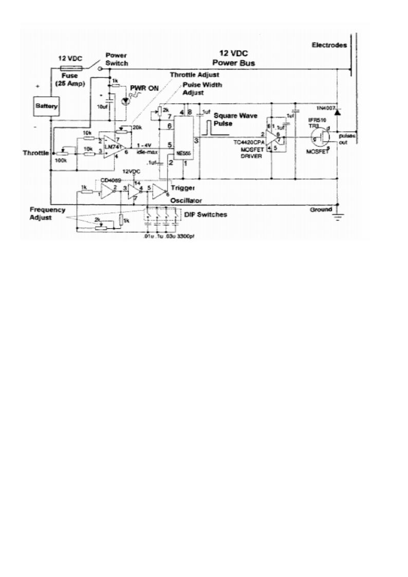
I have a little problem with a design which I have followed. I am novice at this really but have put a circuit board(Breadboard) together to send pulses through a water cell I have designed. My main problem is the frequency cycles being achieved, they are 20khz I believe, I want to achieve 1 to 10Mhz. Please could you advise me to the best ways forward. I have attached the diagram I followed


Maybe this is in the wrong section, please advise, the project is being done in order to help people in communities. I will discuss if answered!
 

Hi,

Please check the datasheets of NE566 and LM741.. and read this manuel..
It helps you to determine how to get frequency
Thanks
 

Attachments

  • FM.pdf
    1.4 MB · Views: 211

    V

    Points: 2
    Helpful Answer Positive Rating
Hi,

Please check the datasheets of NE566 and LM741.. and read this manuel..
It helps you to determine how to get frequency
Thanks

Do you think the trimming pots could be either removed or upgraded to support the desired frequencies? I appreciate your feedback thanks very much.
 

Hi,

Please check the datasheets of NE566 and LM741.. and read this manuel..
It helps you to determine how to get frequency
Thanks

The NE566N only goes upto 1Mhz, I am looking to go between 1 and 10Mhz. I have 20K trimming pot, so that could work for the resistance aspect. The control voltage would be the way to go on a square wave. Do I even need the LM741? it does help on unwanted oscillations. It needs higher MHz tho!
 

MAX038 can achieve the desired frequency in pwm mode. 15% to 85% variable duty cycle
 

Attachments

  • max038.pdf
    210 KB · Views: 34
Last edited:

MAX038 can achieve the desired frequency in pwm mode. 15% to 85% variable duty cycle

That's it, by the looks of it, thx mate. Is there any schematics for this anywhere? I will look but if you know of a PWM schematic it would save time. Thx again it is definitely where I need to be this.
 

see the datasheet for the DADJ (duty cycle adjust voltage), at 0v the duty cycle is 50%.
 

Attachments

  • hsfglc11.gif
    hsfglc11.gif
    18.3 KB · Views: 65

Status
Not open for further replies.

Part and Inventory Search

Welcome to EDABoard.com

Sponsor

Back
Top