Continue to Site

Welcome to EDAboard.com

Welcome to our site! EDAboard.com is an international Electronics Discussion Forum focused on EDA software, circuits, schematics, books, theory, papers, asic, pld, 8051, DSP, Network, RF, Analog Design, PCB, Service Manuals... and a whole lot more! To participate you need to register. Registration is free. Click here to register now.

Pulse generator with different duty cycle using microcontroller with c code

Status
Not open for further replies.

ruhulamineee

Newbie level 6
Joined
Jul 28, 2012
Messages
11
Helped
1
Reputation
2
Reaction score
1
Trophy points
1,283
Activity points
1,357
Hello Every One,

can i use atmega8 for pulse generator in c programing with different duty cycle like 10%, 30%, 50%.

my code was:

if(adc(0)==1){PROTB.0=1; delay_ms(15); PORTB.0=0;delay_ms(5)};
if(adc(1)==1){PROTB.1=1; delay_ms(14); PORTB.1=0;delay_ms(6)};

but its not working according to my duty cycle. how can i crate proper duty cycle.

Thank u
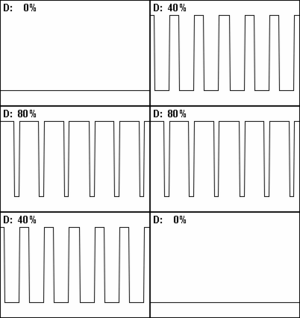
 

PWM_duty_cycle_with_label.gif
In a periodic event, duty cycle is the ratio of the duration of the event to the total period of a signal.
duty cycle D=a/b
where
a is the duration that the function is active.
b is the period of the function.

if the delays are according to the formula u can get the exact duty cycle
 
Last edited:

Thanks for the information kvtal,

for the 50 Hz signal, Time Period is 20ms. According to desired system. for 75% duty cycle it is needed high for 15ms and low for 5ms. again for 70% duty cycle it is needed high for 14ms and low for 5ms.

the code was:
#include <mega8.h>

#include <delay.h>

#define ADC_VREF_TYPE 0x00

// Read the AD conversion result
unsigned int read_adc(unsigned char adc_input)
{
ADMUX=adc_input | (ADC_VREF_TYPE & 0xff);
// Delay needed for the stabilization of the ADC input voltage
delay_us(1);
// Start the AD conversion
ADCSRA|=0x40;
// Wait for the AD conversion to complete
while ((ADCSRA & 0x10)==0);
ADCSRA|=0x10;
return ADCW;
}

// Declare your global variables here

void main(void)
{

// Declare your local variables here

// Input/Output Ports initialization
// Port B initialization
// Func7=In Func6=In Func5=In Func4=In Func3=In Func2=In Func1=Out Func0=Out
// State7=T State6=T State5=T State4=T State3=T State2=T State1=0 State0=0
PORTB=0x00;
DDRB=0x03;


while (1){
if(read_adc(0)>0){PORTB.0=1; delay_ms(15); PORTB.0=0;delay_ms(5);};
if(read_adc(1)>0){PORTB.1=1; delay_ms(14); PORTB.1=0;delay_ms(6);};
};
}

Ans: for 75% duty cycle and 70% duty cycle receptively


why this is happing and how do i get exact duty cycle where frequency is constant 50H
 

what is happening i can not see the images
 

it could be
while (1){
if(read_adc(0)>0){PORTB.0=1; delay_ms(15); PORTB.0=0;delay_ms(5);}; // for 75% duty cycle
if(read_adc(1)>0){PORTB.1=1; delay_ms(14); PORTB.1=0;delay_ms(6);}; // for 70% duty cycle
};


but its not working. is there any way to get perfect duty cycle as i wish.
 

Status
Not open for further replies.

Part and Inventory Search

Welcome to EDABoard.com

Sponsor

Back
Top