Continue to Site

Welcome to EDAboard.com

Welcome to our site! EDAboard.com is an international Electronics Discussion Forum focused on EDA software, circuits, schematics, books, theory, papers, asic, pld, 8051, DSP, Network, RF, Analog Design, PCB, Service Manuals... and a whole lot more! To participate you need to register. Registration is free. Click here to register now.

Problem with connecting supercapacitors in series and getting output from it

Status
Not open for further replies.

Sujith Zis

Newbie level 3
Joined
Jan 17, 2014
Messages
4
Helped
0
Reputation
0
Reaction score
0
Trophy points
1
Activity points
33
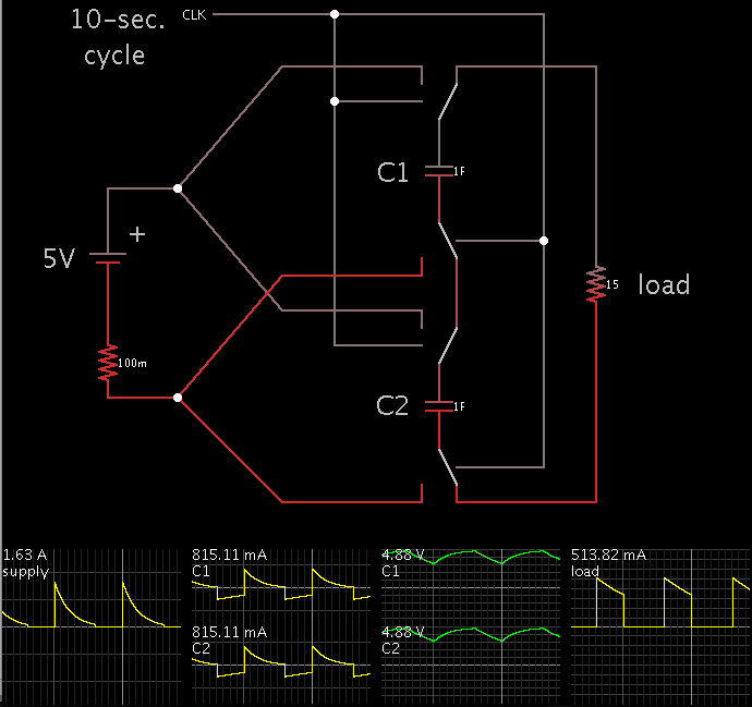
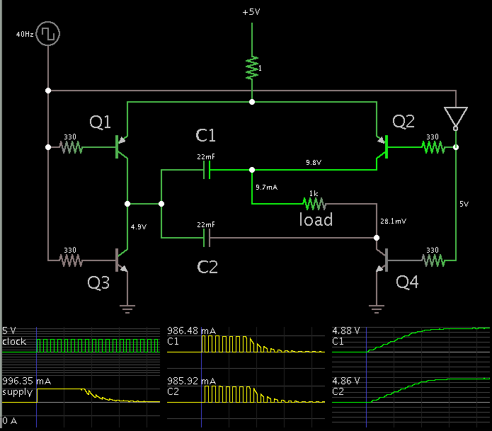
I needed to make a supercap battery bank circuit with >>5V input connected to, two 5.4V supercapacitors connected in series , and output from supercapacitors with on/off switch.<< Its harder the way I did it


also will i be able to get 10V Vout after fully charging the supercapacitors
 

In theory yes you will 10 volts out after fully charge but you have to becareful...if the two caps are of different (capacitance and leakage resistance), most likely it is because no 2 components are identical in real life, you can blow up the caps.
 

Passive networks can insure the voltage is distributed evenly across the supercapacitors and prevent overvoltage. The issue is efficiency and potential loss in the networks. It seems connecting or disconnecting the network appropriately during charging, storing and discharging could reduce this problem. For example, a simple case would be attaching a resistor divider in parallel with the capacitors during charging. This will keep the voltage on the caps to within the accuracy of the resistors. Then, switching out the network (mechanically or electrically) during storage. There are more complex schemes out there. Try searching on something like "uniformly charging supercapacitors".
 

Will it be okay if. I used 3 pole double throw switches

So that charging in parallel and using in series can be accomplished

Also can I get some help regarding prevention of unnecessary discharge of the super caps
 

by putting resistor in parallel with the caps to help keep the charge the same would just be a waste of energy because the resistor would just be eating it up.
 

A single 3PDT switch will do what you want.

Screenshot:


The capacitors charge in parallel, then discharge in series. They will charge to the same 5V.

However you must watch for them discharging unevenly, because a lesser cap would discharge first and be forced to reverse polarity by the stronger cap.

A switch is not absolutely necessary at the bottom lead of C2 (even though my simulation shows a switch there).
 

In my previous post (#3), I missed the requirement to charge for 10V using a 5V source. In this case, balancing the capacitors during the charging phase does not apply since the capacitors are either charged individually or in parallel (see the concept in #6) from the same voltage source. Then, the problem becomes how to maintain balance during storage when unequal leakage currents will unbalance the capacitors over time. If the capacitors are kept at equal voltage during the storage phase, then, during the discharge phase, you can get the most energy out before any imbalance can cause reverse charging (see post #6). So, some sort of passive or active circuit is used to maintain equal voltage between the capacitors. These networks basically transfer charge between the capacitors to keep them at the same voltage. Yes, there is energy loss but hopefully more of the energy can be used in the end.

BTW, in practice, when going from a lower voltage (5V) to a higher voltage (10V), are switching schemes used or is a boost converter used to increase the lower voltage before charging the caps?
 
Last edited:

In case this could work for you...

An H-bridge alternately applies the supply V to one capacitor during one-half of the cycle, then to the other capacitor during the other half of the cycle.

The caps are connected at one end, so that a load across the opposite ends receives twice the supply V.


There is a glitch with this arrangement of NPN's and PNP's. (It does not happen with mosfets).
As the caps reach full charge, a 'rogue' current flows in and out of some bias terminals, and around a large loop.
If you use transistors, and find this glitch is a problem, then you may want to install some kind of buffered bias.
 

Status
Not open for further replies.

Part and Inventory Search

Welcome to EDABoard.com

Sponsor

Back
Top