Continue to Site

Welcome to EDAboard.com

Welcome to our site! EDAboard.com is an international Electronics Discussion Forum focused on EDA software, circuits, schematics, books, theory, papers, asic, pld, 8051, DSP, Network, RF, Analog Design, PCB, Service Manuals... and a whole lot more! To participate you need to register. Registration is free. Click here to register now.

PIC16F877A TIMER1 Problem

Status
Not open for further replies.

wuiven64

Newbie
Joined
Nov 24, 2017
Messages
1
Helped
0
Reputation
0
Reaction score
0
Trophy points
1
Activity points
25
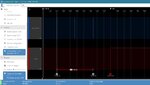
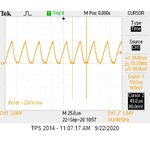
Hi. I'm using PIC16F877A with 20 MHz crystal and PICkit 2 programmer to generate a 180 kHz square wave using TIMER1. However, the waveform that I obtained from Tektronix TPS2014 oscilloscope s not the desired waveform. Besides that, the measured frequency from the oscilloscope is far from the desired frequency. I have attached the code and waveform that capture from the oscilloscope. Kindly give some advice. Thanks.

Code to generate 180 kHz square wave using TIMER1. The compiler is CCS C compiler Ver. 5 demo:
Code:
#include <TIMER1.h>

#INT_TIMER1
void timer1_isr(void)
{
   output_toggle(PIN_B0);
   clear_interrupt(INT_TIMER1);
   set_timer1(65508);
}

void main()
{
   setup_timer_1 ( T1_INTERNAL | T1_DIV_BY_1 ); // Internal clock and prescaler 1
   set_timer1(65508);                           // Preload value
   clear_interrupt(INT_TIMER1);                 // Clear Timer1 interrupt flag bit
   enable_interrupts(INT_TIMER1);               // Enable Timer1 interrupt
   enable_interrupts(GLOBAL);                   // Enable global interrupts
   output_low(PIN_B0);

   while(TRUE) ; // Endless loop
}
 

Attachments

  • TIMER1 V2.jpg
    TIMER1 V2.jpg
    34.7 KB · Views: 100
Last edited by a moderator:

Hi,

Show a photo where we can see both scope connections.

***********

There are many tutorials online, there are youtube videos, there are online timer setup tools.
Why don't you use them?

You even did not use a paper and a pencil to draw the clock and the expected output.
All we professionals use them... every day.
So it's no surprise.

********

20MHz input. This is divided by four as timer/counter input. Thus the counter runs with 5MHz.
Now you set the timer to 65508. It takes 28 count for the timer to overflow.
Then the output gets toggled by software. Let's say it generates the falling edge.
... at next interrupt it generates the rising edge
... at next interrupt it generates the falling edge
--> How much time does it take from falling edge to the next falling edge?

But more detailed:
What indeed happens.
* You se the timer to 65508
* it takes 28 clock ticks to raise the interrupt
* it takes unknown time (t1) for the microcontroller to to enter the ISR (unknown as long as you don't study the microcontroller datasheet)
* it takes unknown time (t2) for the ISR software to store variables on the stack (unknown --> ASM code)
* it takes unknown time (t3) to perform the "toggle" --> ASM
* it takes unknown time (t4) to perform the "clear interrupt" --> ASM
* it takes unknown time (t5) to perform the "set timer --> ASM

Thus the whole timing for one fullwave output is:
2 x (28 counter clocks + t1 + t2 + t3 + t4 + t5)

***

So the much more accurate software solution is to use the compare feature of the timer1:
Just increase the compare register on every interrupt by 28/2=14.
Thus the timing is not determined by the processing time (t1 ... t5) anymore.

But the most accurate an low jitter method is to let the microcontroller internal hardware generate the signal.
Read about PWM or waveform generation.
No need for processing power (except stup). No ISR needed. Perfect f_out = f_xtal / ( 4 × 2 × 14)

Klaus
 

There is no need to use interrupts. Why not use the PICs built in PWM, if it can provide the desired frequency?
 

If you must use a timer(and PWM is by far the better way to go) then can you use Timer2 which is a more 'recent' hardware version with PR registers.
Another way around the latency involved with interrupts is to remember that the timer counter will still be incrementing until you get to reset it in the ISR. Therefore if you use something along the lines of (pseudocode):
Code:
TIMR1 = TimerValue + TMR1
where TimerValue is whatever you calculate you need - 65508 by rour calculation - and this will automatically take the latency into account.
(With that device you might be able to treat the TMR1 register as a 16-bit value - I've not used that MCU so I'm not certain. Even if you need to use 8-bit reads then the chances are you won't have incremented TMR1H.)
Susan
 

hello,
your oscillo screen capture show only some noise à 38Khz 30mV
it is not a PORT output .


using Timer is not possible because to much time used for
the interrupt treatment itself
2,8 à 3,6µS only for interrupt IN/OUT at 20Mhz
180Khz means Output ON for 2,77 µS then OFF for same time
if dutycyle is 50%

If your MCU has no other task to do
a simple loop
in asm could be used to control the periode with One cycle of 0,2µS accuracy
goto $1 => 2 cycles => 0.4µS
or a NOP => 1 cycle => 0.2µS

this asm code into mikroc ...

Code:
_asm{
        ICI:
          BSF PORTD,7 // 0
         GOTO   $+1;  // 2 x 0.2=0.4µS
         GOTO   $+1;
         GOTO   $+1;
         GOTO   $+1;
         GOTO   $+1;
         GOTO   $+1;
         GOTO   $+1;
         GOTO   $+1;
         GOTO   $+1; //  <2 µS
         BCF PORTD,7   ; //0
         GOTO   $+1;
         GOTO   $+1;
         GOTO   $+1;
         GOTO   $+1;
         GOTO   $+1;
         GOTO   $+1;
         GOTO   $+1; //1.6 µS
         NOP ;   // fine adjutement
         GOTO   ICI;// +0.6 uS
       }

gives 135 Khz , Ton=3,8µS  Toff=3.56µS  on Tektronics TDS 2002C
amplitude 4.64V

adjust the number of GOTO $+1 or
add NOP
to obtain 180Khz

i didn't test PWM case ...
On newer PIC18 there is a Freqency generartor with dutycyle of 25,50,75%
100% Hardware, only setting register values , then contineous output of signal.
so the MCU can do other task..
 

I checked the data sheet for that device and it certainly has a PWM module that is quite capable of generating the desired frequency. It does also use Timer2. Therefore software is only required to set it up - it is all hardware after that.
Without knowing what other modules the OP is using it is hard to say if this is a useful option or not, but it certainly is an option.
Susan
 

hello,

I checked the data sheet for that device and it certainly has a PWM module that is quite capable of generating the desired frequency. It does also use Timer2. Therefore software is only required to set it up - it is all hardware after that.
Without knowing what other modules the OP is using it is hard to say if this is a useful option or not, but it certainly is an option.
Susan


yes , you are right !
i tested it , with a MicroChip IRDA demo board with a MCU 16F877, Q=20MHz
using MikroC 7.60

the PWM RC2 output give an permanent output of near 180KHz
with duty cycle adjustable !
and no big ressources used for that .. because it is a hardware function.
i added UART output, Analog measure, and LCD display in my test.

i also used MCU Register instead of MikroC PWM library !
so more portable software.

Code:
SQA=1;
  TRISC2_bit=0;   // RC2 PWM output
  CCP1CON=0x0C;
  // TMR2 used for CCP1 PWM output
  T2CON = 0b00000100;     // TMR2 ON, postscale 1:1, prescale 1:1
  // at 20/ 4 Mhz tick=0,2µS    180 Khz => 5.55µS  =>  27x0.2=5.4µS
  PR2 = 27-1;     // PR2 set to total PWM period of 10 ticks (5.5uS)  at 20Mhz
  pwmval=127;  // 50%
  CCPR1L=pwmval;  //PWM1_Set_Duty(pwmval) ;
  SQA=1;  // trigger ON , for RC2 signal capture via SQA Logic Analyser
  TMR2ON_bit=1; // // PWM1_Start();
  SQA=0;  // trigger OFF

an Logic Analyser connected on RC2 ..
SQA=RD1 is used as a trigger to strat the RC2 signal capture
 

Attachments

  • PWM_180Khz_16F877_2020_09.jpg
    PWM_180Khz_16F877_2020_09.jpg
    95.4 KB · Views: 98

Status
Not open for further replies.

Similar threads

Part and Inventory Search

Welcome to EDABoard.com

Sponsor

Back
Top