milan.rajik
Banned
Page 9 of datasheet mentions
2.4 Data interface
SZ05-ZigBee Wireless Module has standard interface of RS232, RS485 or TTL in the hardware. Serial
RS232 includes TX2, RX2 and GND. RS485 contains TX2(A+), RX2(B-). TTL interface is TX1 and RX1,
and the level of TTL is 3.3V
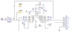
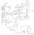
TTL TX1 and RS1 are the 3.3V TTL pins. It has to be cross connected to PIC UART Rx and Tx pins. Zigbee RS1 to PIC Tx and Zigbee TX1 to PIC Rx. You can't directly connect it to PIC as PIC is 5V TTL device. See if you can power the PIC with a 3.3V power supply. If yes, you can then use the above connection else if PIC doesn't run at 5V then you need a voltage level translator between Zigbee 3.3V TTL pins and PICs 5V TTL pins.
Another method is to use Zigbees RS232 pins (TX2, RX2) to connect to PIC UART pins. For this A MAX232 is needed. MAX232 circuit is provided in MAX232 datasheet. If you don't want to use MAX232 you can use RS232 to TTL Converter. Connect the RS232 side of converter to Zigbee RS232 port and TTL side to PIC. Whether you use RS232 ot TTL the GND pin of Zigbee should be connected to PIC circuit ground.
Have you configured Zigbee properly?
2.4 Data interface
SZ05-ZigBee Wireless Module has standard interface of RS232, RS485 or TTL in the hardware. Serial
RS232 includes TX2, RX2 and GND. RS485 contains TX2(A+), RX2(B-). TTL interface is TX1 and RX1,
and the level of TTL is 3.3V
TTL TX1 and RS1 are the 3.3V TTL pins. It has to be cross connected to PIC UART Rx and Tx pins. Zigbee RS1 to PIC Tx and Zigbee TX1 to PIC Rx. You can't directly connect it to PIC as PIC is 5V TTL device. See if you can power the PIC with a 3.3V power supply. If yes, you can then use the above connection else if PIC doesn't run at 5V then you need a voltage level translator between Zigbee 3.3V TTL pins and PICs 5V TTL pins.
Another method is to use Zigbees RS232 pins (TX2, RX2) to connect to PIC UART pins. For this A MAX232 is needed. MAX232 circuit is provided in MAX232 datasheet. If you don't want to use MAX232 you can use RS232 to TTL Converter. Connect the RS232 side of converter to Zigbee RS232 port and TTL side to PIC. Whether you use RS232 ot TTL the GND pin of Zigbee should be connected to PIC circuit ground.
Have you configured Zigbee properly?