Continue to Site

Welcome to EDAboard.com

Welcome to our site! EDAboard.com is an international Electronics Discussion Forum focused on EDA software, circuits, schematics, books, theory, papers, asic, pld, 8051, DSP, Network, RF, Analog Design, PCB, Service Manuals... and a whole lot more! To participate you need to register. Registration is free. Click here to register now.

[PIC] PIC16F877A MCLR problem.

Status
Not open for further replies.

Manjuhb

Newbie level 6
Joined
Dec 2, 2015
Messages
14
Helped
0
Reputation
0
Reaction score
0
Trophy points
1
Activity points
149
Hi All,

I have connected the MCLR pin of PIC16F877A to VCC through 10K ohm resistor, but when I turn on the MCU the LCD is not displaying the second line until I touch the MCLR pin to GND point through a wire if once I touch then it will work properly until net power though main. Can any one tell me what is the problem please.

Thanks,
Manjunath H B
 

Are you using external crystal? Are there 22pF capacitors along with crystal?
Do you have 100nF capacitor between VCC and GND?
 

hello,


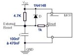
typical reset circuit :

Reset_MCU.jpg

if your power supply takes too long time to reach nominal value ....
you can also use internal MCU power timer feature.. to wait correct FOSC..
 

If the LCD uses a standard controller, it can take over 100mS to initialize after power up. Possibly your 16F877A is writing to it before it is ready. Resetting the PIC will not reset the LCD so it would be ready to accept commands the second time the PIC program runs.

Try adding an additional delay at the start of the PIC program to give the LCD time to 'wake up'.

Brian.
 

Yes I am using external crystal also I have connected the 22pF capacitors across the crystal.

--------------------------------------------------------------------------------

But I am continuously writing the second line of the LCD then it should display later right....? mean aster some 100mS.

--------------------------------------------------------------------------------

Yes I have used 100nF across the VCC and GND also.
 
Last edited by a moderator:

Hi,

After power up the LCD needs an initialisation. This is only done once.

If you try too early to initialize the LCD, then the LCD will not work properly.

Klaus
 

Hello Klaus,

Thanks for replying. But same code is working fine in the other board.
 

Hi,

I believe.


But maybe your timing of initialisation is near the limit.
Maybe you use another power supply, maybe you use another bulk capacitor or have different load currents.
Maybe the LCD has changed.
Maybe the reset circuit has changed.

--> review your power up and initialisation timing with a scope.

Klaus
 

Oh OK OK may be that is the issue some boards it is working some boards it is not working. Thanks I will change the delay timings. Thanks.
 

But I am continuously writing the second line of the LCD then it should display later right....? mean aster some 100mS.
No. Because the first data sent to the LCD is to initialize it. If it isn't receptive to initialization data, the LCD will never work properly, no matter how many characters you write to it afterwards.

Brian.
 

Hi All,

is it is necessary to have 100nF at the MCLR pin because I have just connected the resistor alone.
 

Hi,


With a simple reistor the RESET is inactive as soon as the supply voltage is above 2V (or whatever the RESET pin threshold voltage is)
how do you ensure the ower supply is stable?

A capacitor (with resistor) generates a time delay. Maybe 20ms. Then the supply has 20ms more time to become stable. But it has no precise threshold voltage.

Many microcontrollers have (configurable) built in voltage detectors (brown out circuit) and have built in (configurable) delay befor RESET is deactivated after power up.

A very reliable solution is to use a supervisor circuit like LM809. Precise threshold voltage combined with delay time.

Klaus
 

Status
Not open for further replies.

Similar threads

Part and Inventory Search

Welcome to EDABoard.com

Sponsor

Back
Top