Continue to Site

Welcome to EDAboard.com

Welcome to our site! EDAboard.com is an international Electronics Discussion Forum focused on EDA software, circuits, schematics, books, theory, papers, asic, pld, 8051, DSP, Network, RF, Analog Design, PCB, Service Manuals... and a whole lot more! To participate you need to register. Registration is free. Click here to register now.

Peak detector temperature compensation

Status
Not open for further replies.

Bakez

Member level 1
Joined
Mar 23, 2010
Messages
33
Helped
0
Reputation
0
Reaction score
0
Trophy points
1,286
Activity points
1,613
Hello

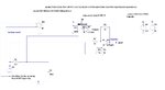
I have a peak detector that detects the peak voltage drop over a resistor that charges a capacitor. Its just an opamp and a diode+ capacitor as you can see, and the capacitor is discharged using the control of the actual gate voltage

However I need to remove the temperature coefficient of the diode, when I calibrate this circuit the change in the voltage drop over the diode ruins my measurement

How can I do this? I read that most peak detector circuits that remove the diode voltage drop mean the opamp goes into saturation and is therefore always slow. I can't have this as I'm detecting peaks that occur about 200nS into a window that only lasts about 800nS.

You can see in the pics I attach

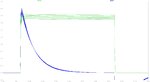
Although with these opamps in the LTSpice simulation, the saturation doesnt appear to cause a problem, I dont think the additional heat generated from always driving the opamp to the rails is acceptable as this circuit will be running 24/7.

I either need to compensate for the temperature or a way to remove the diode voltage drop without driving the opamp into saturation

Does anyone have any ideas?
 

Attachments

  • peak detector resistor.jpg
    peak detector resistor.jpg
    175.6 KB · Views: 143
  • peak detector resistor output.jpg
    peak detector resistor output.jpg
    125 KB · Views: 115

you need to look around for other sample and hold circuits - there are many better ones to hold the peak for you ADC.
 

Well, since op-amp based precision rectifiers are out of option due to saturation delay. You may have to add a good amount of extra circuitry to accomplish the same task without using precision rectifiers. Consider the following alternative:

1. Replace the capacitor C1 with a resistor. Connect an op-amp across the resistor and measure the voltage. Let it be V1
2. Connect an op-amp across the diode and measure the voltage. Let it be Vd
3. Use another amplifier and add the two voltages in the following manner:
V2 = V1 + 2Vd
4. Send this output to hold-capacitor through a diode. So the voltage across the capacitor is
Vc = (V2 - Vd) = (V1 +Vd)
5. Note that V1 + Vd is the desired voltage. The drop across the diode is compensated by adding the term Vd.
6. To minimize temperature discrepancies, use two diodes fabricated on the same IC, so that the temperature of both is nearly the same.
 

The saturation delay might not be a problem if its less than 100nS in these 1000V/us slew rate opamps

I also dont know why the opamp stays in saturation even when i discharge the capacitor
 

I don't think heat generation is a problem in your circuit. Operating saturated has little effect on the current consumption. Are you concerned about power consumption (e.g. battery operation)? If so you could operate the op amps at a lower voltage.

Note that as those high speeds, circuit layout is critical. You need a good ground, preferably a ground plane, with short signal connections and 0.1µF decoupling caps with short leads directly at each power pin to ground. If you do a breadboard, use vector board with a copper plane for the ground.

Edit: I just realized your circuit does not have the diode in the feedback loop so the diode drop is not compensated.
 

Well, since op-amp based precision rectifiers are out of option due to saturation delay. You may have to add a good amount of extra circuitry to accomplish the same task without using precision rectifiers. Consider the following alternative:

1. Replace the capacitor C1 with a resistor. Connect an op-amp across the resistor and measure the voltage. Let it be V1
2. Connect an op-amp across the diode and measure the voltage. Let it be Vd
3. Use another amplifier and add the two voltages in the following manner:
V2 = V1 + 2Vd
4. Send this output to hold-capacitor through a diode. So the voltage across the capacitor is
Vc = (V2 - Vd) = (V1 +Vd)
5. Note that V1 + Vd is the desired voltage. The drop across the diode is compensated by adding the term Vd.
6. To minimize temperature discrepancies, use two diodes fabricated on the same IC, so that the temperature of both is nearly the same.
I have considered doing this

- - - Updated - - -

I don't think heat generation is a problem in your circuit. Operating saturated has little effect on the current consumption. Are you concerned about power consumption (e.g. battery operation)? If so you could operate the op amps at a lower voltage.

Note that as those high speeds, circuit layout is critical. You need a good ground, preferably a ground plane, with short signal connections and 0.1µF decoupling caps with short leads directly at each power pin to ground. If you do a breadboard, use vector board with a copper plane for the ground.
I will try it in saturation

In LTspice it works fine but Im not sure LTspice models the recovery from saturation

I have built another circuit that works on the same resistor under the same time time constraints (an opamp integrator) that works fine, I dont think I had much problem with the layout. Essentially Im just modifying the operation of the opamps on that PCB

- - - Updated - - -

Alternatively I could just buy a diode that is as fast as 1n4148 but with minimal temperature dependence, if one exists....?
 

A faster diode would be a Schottky type such as a BAT54 but they have a similar temperature coefficient.
 
Last edited:

It is repeating but it will be changing every time (and it is the change that I care about, not the absolute value) so I dont think the comparator option that I have read about and I think you are suggesting will work
 

Below is the simulation of a peak-hold circuit using a fast comparator with the diode inside the feedback loop. Comparators do not suffer from any significant saturation delay. Perhaps that would work for you.

Pk Hold.gif
 
  • Like
Reactions: FvM

    FvM

    Points: 2
    Helpful Answer Positive Rating
Looks interesting

But do comparators come in +15/-15?

and also the peak Im measuring probably only lasts for a few nS at best
 

I deal with pulses on the order of ps up to 1 ns and usually just use a Le Croy scope.

But to design a pulse height detector has many sources of measurement error due to impedance mismatch, and parasitic ESL, capacitance.& ESR,

My suggestion is you analyze the linearity requirements and see if you can integrate the result and compute the peak current from the Integrate and hold, then measure, voltage, dump charge and repeat.

THis measures the integral I*dt which is proportional to the peak

Make sense? or need more explanation?

Otherwise, This would be my choice of a 1ns Peak detector. using an Operational Transconductance Amplifier with buffer (OTA)

You don't need the negative peak detector on top which has a bandwidth of 1.5GHz

peak detector.jpg
 

Fast comparators generally operate a lower voltages.

A few ns?? Good luck in detecting that.
You can see the peak I need to detect in the pics

I have a circuit that removes the diode voltage drop but it seems to give out wildly different outputs depending on stabilising capacitors which I dont understand and have no clue about

I will post it later
 

Status
Not open for further replies.

Similar threads

Part and Inventory Search

Welcome to EDABoard.com

Sponsor

Back
Top