Continue to Site

Welcome to EDAboard.com

Welcome to our site! EDAboard.com is an international Electronics Discussion Forum focused on EDA software, circuits, schematics, books, theory, papers, asic, pld, 8051, DSP, Network, RF, Analog Design, PCB, Service Manuals... and a whole lot more! To participate you need to register. Registration is free. Click here to register now.

Output Current control using a 5V DC source

Status
Not open for further replies.

metalmisers

Junior Member level 2
Joined
Mar 4, 2012
Messages
22
Helped
0
Reputation
0
Reaction score
0
Trophy points
1,281
Activity points
1,457
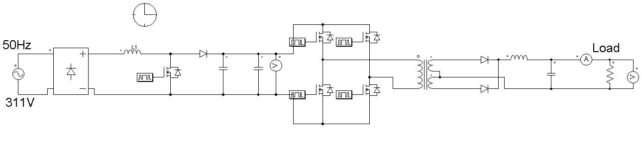
Hello everyone. I am building a SMPS AC/DC power supply using a PFC and a full bridge DC/DC converter. I want to control the output current of the converter using a 5V external power supply. I was thinking of using a BJT in linear mode but found out that the losses would be great, what would you guys recommend? Also, is there an IC which has both full bridge and PFC PWM switching devices? Thanks.
 

You mean you want a current regulated output of the DC/DC converter, or you want an adjustable current limit?

It may be possible to modify the controller of the full bridge DC/DC converter to do that, but it depends on what kind of controller it it.

I believe there are ICs out there that have PFC preregulator and buck converter postregulator capabilities combined, but I don't think they can be easily adapted to a full bridge post regulator (especially if it's a phase shifted full bridge).
 
The adjustable current limit, an external 5v source with control the output current that flows into the load. I think it is the same in the laboratory power supplies. I only drew the basic circuit in psim but haven't selected an IC for it yet, i cant get to understand the working of operation of current limiting in this way, is it like driving a BJT in linear mode?
 

The adjustable current limit, an external 5v source with control the output current that flows into the load. I think it is the same in the laboratory power supplies. I only drew the basic circuit in psim but haven't selected an IC for it yet, i cant get to understand the working of operation of current limiting in this way, is it like driving a BJT in linear mode?
There are a few ways to implement variable current limits. The most efficient is to actually build that functionality into the switching DC/DC converter itself. Could you post a schematic of what you have?


I havent written the names of everything else. Thanks a lot.
 

Status
Not open for further replies.

Similar threads

Part and Inventory Search

Welcome to EDABoard.com

Sponsor

Back
Top