Continue to Site
Follow along with the video below to see how to install our site as a web app on your home screen.
Note: This feature may not be available in some browsers.
Kindly, How can I simulate the input capacitance of the operational amplifier ??
Hello Erikl
may be you understand my question wrong, I dont want to simulate the input Impedance, I want the input capacitance of the CMOS Op-Amp
if I am still thinking :wink::idea::idea: then the value of the impedance is in Ohm, I need the capacitive value in Farad
unless if you want me to do this XC = 1/2.Pi.Cin , then it is Ok for me now .
then please give me the circuit configuration for simulating it
many thanx
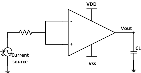
... I shorted the both inputs of the op-amp, is that right or I shold do the same connection of the bode blod setup ?
Hello Junus.
If you would like to measure input capacitance with the RC method you describe, you will need to use a voltage pulse, not an AC current source.
As for which terminal to measure, I guess one terminal will be at a DC reference voltage and the other at the signal source, so that only one terminal is driven. Given that, you should only measure the capacitance of one terminal of the opamp. Don't forget to bias both terminals correctly, as in the real application, or else you will get faulty results.
... I calculate the input capacitance at when the voltage drop by -3db from Cin= 1/2.Pi.Rin.f(-3db) as seen in the image I attached.
I think this is a trust way to simulate or measure the input capacitance, otherwise I will get the complex input impedance (resistive and capacitive )
Such a test bench setup is completely meaningless, as it wouldn't represent any application (it's a connection for common mode rejection measurement).
 ;-)
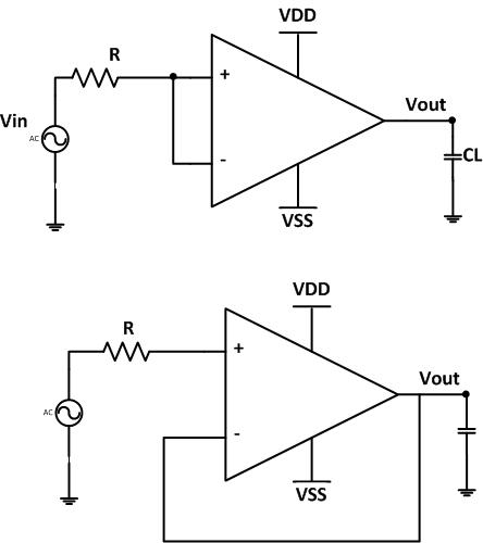
;-)Ok. Next time you'd want to be a bit more thorough with your info. Such errors just create unnecessary answers. :-(I am sorry guys I mean to put in the picture a voltage source not a current source
In this case you'd actually use a transient simulation of course. And your series resistance Rs should be small against the resistance Rp in parallel to the node to be measured: Rs « Rp .I think you got my idea of introducing like a low pass filter to detect the input capacitance
")
Ok. Next time you'd want to be a bit more thorough with your info. Such errors just create unnecessary answers. :-(
In this case you'd actually use a transient simulation of course. And your series resistance Rs should be small against the resistance Rp in parallel to the node to be measured: Rs « Rp .
Hi Junus, I think the whole thread - up to now - is a bit confusing since you didn`t tell us what you really want.
OK- in your first posting you speak about the "input capacitance" of an opamp.
But remember: At first,the opamp has TWO inputs and - secondly - it can be (and normally is) operated with negative feedback.
Thus - what do you need? Input capacitance at which input in which configuration ?