Continue to Site

Welcome to EDAboard.com

Welcome to our site! EDAboard.com is an international Electronics Discussion Forum focused on EDA software, circuits, schematics, books, theory, papers, asic, pld, 8051, DSP, Network, RF, Analog Design, PCB, Service Manuals... and a whole lot more! To participate you need to register. Registration is free. Click here to register now.

need help ,verilog code for Program counter ?

Status
Not open for further replies.

vead

Full Member level 5
Full Member level 5
Joined
Nov 27, 2011
Messages
285
Helped
3
Reputation
6
Reaction score
3
Trophy points
1,298
Location
india
Visit site
Activity points
3,815
hello,
I need help to understanding following verilog code for PC

Code Verilog - [expand]
1
2
3
4
5
6
7
8
9
10
11
12
13
14
15
16
17
18
19
20
21
22
23
24
25
26
27
28
29
30
31
32
33
34
35
36
37
38
39
40
41
42
43
44
module PC(clk  , instruction ,  zero , branch , jump , pc );
input clk ;
input[31:0] instruction ;
reg[31:0] npc;
input zero ;
input jump ;
input branch ;
wire[31:0] pcInc;
wire[31:0] Branch1 ;
wire[15:0] address;
wire[31:0] branchAdd;
reg[31:0] mux1; 
wire select1 ;
wire[31:0] jumpAdd ;
output [31:0] pc ;
reg [31:0] pc ;
 
 
assign select1 = branch & zero ;
assign pcInc = pc + 4 ;
assign address = instruction[15:0];
assign Branch1 =  {{16{address[15]}},address[15:0]} ;   // sign extension
assign branchAdd = pcInc + ( branch << 2 ) ;
 
always@( branchAdd or pcInc or select1  ) 
begin
    if ( select1 == 1 )
        mux1 = branchAdd ;
    else
        mux1 = pcInc ;
end
 
assign jumpAdd = ( instruction[25:0] << 2 );
 
always@ ( jump or jumpAdd or mux1 )
begin
    if ( jump == 1 ) 
        npc = jumpAdd ;
    else
        npc = mux1;
end
 
always @(posedge clk )
    pc <= npc;


I understand how UP counter work but I don't understand how does PC work with different input ( example jump, branch )
?
 

This code seems to be incomplete, since neither address nor Branch1 are used in the code.

But in brief,

* If the jump control signal is high, the value of the program counter will be incremented by (instruction[25:0] * 4).

* Else, if both the branch and zero signals are high, the value of the program counter will be incremented by 8.

* Else, the program counter is incremented by 4, which is what is normally done when no jump or branch occurs.

As to specifically why the designer chose to do things this way, you would have to ask them. This is only a very small snapshot of a much bigger view.

r.b.
 
  • Like
Reactions: vead

    vead

    Points: 2
    Helpful Answer Positive Rating
This code seems to be incomplete, since neither address nor Branch1 are used in the code.


As to specifically why the designer chose to do things this way, you would have to ask them. This is only a very small snapshot of a much bigger view.

r.b.

Ok Look the following code for up counter
Code:
 module up_counter    (
   out     ,  // Output of the counter
   enable  ,  // enable for counter
  clk     ,  // clock Input
  reset      // reset Input
  );
  //----------Output Ports--------------
      output [15:0] out;
  //------------Input Ports--------------
      input enable, clk, reset;
  //------------Internal Variables--------
      reg [15:0] out;
  //-------------Code Starts Here-------
 always @(posedge clk)
  if (reset) begin
    out <= 16'b0 ;
  end else if (enable) begin
  out <= out + 1;
  end
  endmodule

what should I have to do for jump and branch ?
 

Ok Look the following code for up counter

I did look at it. That code will almost certainly generate latches.

what should I have to do for jump and branch ?

Uh, I thought I was pretty clear in my response above about what you had to do, even to the degree that I made the starred lines into an if / else if / else statement.

To reiterate, You would have to change the out <= out + 1 section to add either 4,8, or instruction[25:0] <<2 rather than 1, based on the conditions I described.

However, do you understand the program counter code enough to know that this behaviour is what you want for your purposes?

r.b.
 

Ok Look the following code for up counter
Code:
 always @(posedge clk)
  if (reset) begin
    out <= 16'b0 ;
  end else if (enable) begin
    out <= out + 1;
  end

I did look at it. That code will almost certainly generate latches.

I'm looking at the same code and that snippet will not generate latches. Perhaps you believe that you have to implement a synchronous reset and enable register like this?:
Code:
always @ (posedge clk)
  if (reset) begin
    out <= 16'b0;
  end else if (enable) begin
    out <= out + 1;
  end else begin
    out <= out;
  end

The out <= out; is unnecessary, without the else statement out just holds it's previous value (and it's using flip-flops to do this)
 
  • Like
Reactions: vead

    vead

    Points: 2
    Helpful Answer Positive Rating
I did look at it. That code will almost certainly generate latches.


Uh, I thought I was pretty clear in my response above about what you had to do, even to the degree that I made the starred lines into an if / else if / else statement.

To reiterate, You would have to change the out <= out + 1 section to add either 4,8, or instruction[25:0] <<2 rather than 1, based on the conditions I described.

I did copy and paste code. I don't understand what you mean by this line the out <= out + 1 section to add either 4,8, or instruction[25:0] <<2 rather than


However, do you understand the program counter code enough to know that this behaviour is what you want for your purposes?
r.b.[/QUOTE]actually I want to make program counter for following circuit, I have spend lot of time , then I looked verilog code, I think this code may be help
circuit data transfer.png

I have little bit knowledge about verilog. I just want learn about branch and jump instruction, how my Pc know that it need to load new address ?
 

@ads-ee


I stand corrected. It synthesize without latches using Xilinx tools.

Nonetheless, since you asked, this is the way I would write it (just the core code shown):


Code Verilog - [expand]
1
2
3
4
5
6
7
8
9
10
11
12
13
14
15
16
17
18
19
logic [15:0]       out_next;
 
always_ff @ (posedge clk) begin
   if (reset == 1'b1) begin
     out <= '0;
   end
   else begin
      out <= out_next;
   end
end
 
always_comb begin
   if (enable == 1'b1) begin
      out_next = out + 1;
   end
   else begin
     out_next = out;
   end
end


@vead

What I mean is, rather than increment your counter by one each clock , you will increment it by 4, 8 or instruction[25:0]<<2 depending on the state of the control signals. you would create an if else structure which included out <= out + 4, out <= out + 8 and out <= out + (instruction[25]<<2)

This is base Verilog,and you have plenty to go on

r.b.
 

I'm not sure what you are trying to accomplish, your question is not clear.

Are you trying to use some PC code you found from the internet?
Are you trying to implement your schematic?

I would consider the code you posted very low quality code, which is typical of the code found on the internet. Most of the code you'll find off the internet are written by students and is therefore almost always of the poorest quality (almost by definition;-)). If you wrote the code you posted based on the schematic in post #6 then you haven't even close to implemented the schematic. You also haven't defined how all those unconnected signals on ICs is supposed to be controlled.

I can see from the schematic you've got some cross connected multiplexing going on between the Register R1 and the Accumulator, so what determines which path is connected?

I also don't get why you even posted the up_counter code as it isn't used anywhere in the PC code you posted, so any discussion about using + 4 instead of a + 1 is meaningless.

Perhaps you only posted snippets or edited the code you posted. As you've stated you're a novice Verilog coder, you should perhaps spend time going over Verilog tutorials or read a book on Verilog before editing code (for posting), when you don't fully understand the language. I suggest you post the original code in full context or a point us to the link where we can look at the code you found.

- - - Updated - - -


Code Verilog - [expand]
1
2
3
4
logic [15:0]       out_next;
 
always_ff @ (posedge clk) begin
always_comb begin


I've gotten used to using the least common denominator for coding anything as every time I add SV to anything some tool ends up breaking.

On a side note, I think the addition of always_ff and always_comb was a bit of a cop-out as it was added to ensure that cr@p code compiles according to the intent of the coder. Personally I'd rather code it correctly in the first place and not have the tools force it to be correct.
 
Last edited:

I have never had issues using SV, and I really appreciate some of the new constructs. However I do not understand the reason for adding always_ff , etc. The only thing I can think of offhand is that It seems to aid code checking tools like Spyglass, which is a requirement in our process.

r.b.
 

I'm not sure what you are trying to accomplish, your question is not clear.
i want to make program counter that will do following things
1. program counter increment by 1
2. program counter will load jump address
3. program counter will load branch address

Are you trying to use some PC code you found from the internet?
yes actually I want to know logically how PC load with new address.

Are you trying to implement your schematic?
yes I drawn schematic for ALU, register, memory.next I want to add program counter.

I would consider the code you posted very low quality code, which is typical of the code found on the internet. Most of the code you'll find off the internet are written by students and is therefore almost always of the poorest quality (almost by definition;-)). If you wrote the code you posted based on the schematic in post #6 then you haven't even close to implemented the schematic. You also haven't defined how all those unconnected signals on ICs is supposed to be controlled.
Perhaps you only posted snippets or edited the code you posted. As you've stated you're a novice Verilog coder, you should perhaps spend time going over Verilog tutorials or read a book on Verilog before editing code (for posting), when you don't fully understand the language. I suggest you post the original code in full context or a point us to the link where we can look at the code you found.

here is link for code **broken link removed**


I also don't get why you even posted the up_counter code as it isn't used anywhere in the PC code you posted, so any discussion about using + 4 instead of a + 1 is meaningless.

I posted that code because If I know the basic up counter than how I can make loadable counter? I have seen we use some multiplexer to select new address. I though I have to start with basic so I posted that code

how do you know that it generate ff or latches ?
 

FYI, you created a broken link, the URL got edited when you added it. (I fixed it when it failed to open).

Are you Rojin on that site? Is that your code?

If you are Rojin, how many forums did you cross posted this on? I would suggest NOT posting the exact same question on multiple forums. I really dislike the spam posting mentality, it tells me that the poster doesn't care about other people's time as they don't care where they get their answer first. If they get the answer on forum A then they never revisit forum B and posters on forum B are wasting their time responding to the Hit-n-Run question. So don't cross post

If you are not Rojin then I would seriously suggest not using that code as a reference. There are some MIPs implementations on OpenCores you would be better off using as examples, though I won't go so far as to say they are great examples of good design or coding practices.

vead said:
1. program counter increment by 1
That depends on if you're PC is counting by bytes/words/long_words. The previous code snippet seems to have 4 bytes per instruction and the PC is a byte count. So it increments by 4 as each instruction is 4 bytes in length.

vead said:
I posted that code because If I know the basic up counter than how I can make loadable counter? I have seen we use some multiplexer to select new address. I though I have to start with basic so I posted that code
You need to read a good Verilog book/tutorial if you have to ask this question...

Code Verilog - [expand]
1
2
3
4
5
6
7
8
// counter with load priority, i.e. doesn't need an enable to load.
always @ (posedge clk) begin
  if (load) begin
    count <= the_value_to_load;
  end else if (enable) begin
    count <= count +1;
  end
end


FYI, you created a broken link, the URL got edited when you added it. (I fixed it when it failed to open).

Are you Rojin on that site? Is that your code?

If you are Rojin, how many forums did you cross posted this on? I would suggest NOT posting the exact same question on multiple forums. I really dislike the spam posting mentality, it tells me that the poster doesn't care about other people's time as they don't care where they get their answer first. If they get the answer on forum A then they never revisit forum B and posters on forum B are wasting their time responding to the Hit-n-Run question. So don't cross post

I am not Rojin , If you want to confirm then you can check my old threads and profile

If you are not Rojin then I would seriously suggest not using that code as a reference. There are some MIPs implementations on OpenCores you would be better off using as examples, though I won't go so far as to say they are great examples of good design or coding practices.

I am not serious about that code because I need basic idea for program counter. I have schematic diagram for ALU, register, accumulator, and I want to add program counter. i want to implement schematic diagram for PC. I am searching from 1 week , All is very complex, I thought that verilog code may be give some idea , as my learning style. I make small circuit then I add another function then another function.

That depends on if you're PC is counting by bytes/words/long_words. The previous code snippet seems to have 4 bytes per instruction and the PC is a byte count. So it increments by 4 as each instruction is 4 bytes in length.


You need to read a good Verilog book/tutorial if you have to ask this question...
I don't understand what I do ? what I need to do ? I need to implement with logic Ic or verilog code ?
 

I am not Rojin , If you want to confirm then you can check my old threads and profile
Okay, it wasn't that apparent as you question and the stack exchange question were identical. You should probably make more of an effort than cut and paste another persons question.

vead said:
I am not serious about that code because I need basic idea for program counter. I have schematic diagram for ALU, register, accumulator, and I want to add program counter. i want to implement schematic diagram for PC. I am searching from 1 week , All is very complex, I thought that verilog code may be give some idea , as my learning style. I make small circuit then I add another function then another function.
Look at one of the opencores implementation of a 8051 or the Xilinx Picoblaze. Small 8-bit processors are about as simple as you can get. Neither of those processors have any branch prediction or anything all that complex. There are also quite a few tutorials on building 8-bit processors in an FPGA, if you still haven't found them after a week of searching, then you need to learn how to perform a web search.

vead said:
I don't understand what I do ? what I need to do ? I need to implement with logic Ic or verilog code ?
huh? I don't understand what you mean by these questions...
Do you really need someone to tell you to do some more studying, read books on Verilog, read books on digital design, etc? Also why do you need to implement it in a logic IC? Every processor made uses some sort of HDL to implement the design.

Based on what you've said so far, I think you need to brush up on the basics of digital design.
 

Okay,

Look at one of the opencores implementation of a 8051 or the Xilinx Picoblaze. Small 8-bit processors are about as simple as you can get. Neither of those processors have any branch prediction or anything all that complex. There are also quite a few tutorials on building 8-bit processors in an FPGA, if you still haven't found them after a week of searching, then you need to learn how to perform a web search.
I told you in my previous post opencores implementation of a 8051 is very complex for me. I am learning some basic
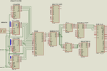
Untitledjjkh.png
this is incomplete diagram. I have not connected input of program counter. I dont understand how to connect program counter for jump and branch instruction. thats why I am looking some example .
 

Then look at the pacoblaze (i.e. picoblaze clone) its really really simple. Just look in pacoblaze.v and search for program_counter_next along with program_counter_source to see how the program counter is updated.

If you can't follow how the program counter works from that example, then I can't help you. You should go talk with your instructor or maybe take a class that concentrates on basic logic design.
 
Status
Not open for further replies.

Part and Inventory Search

Welcome to EDABoard.com

Sponsor

Back
Top