barbaro
Member level 3
Hi mister_rf
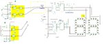
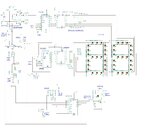
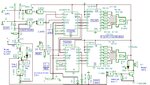
I finally have it working, it's just that my breadboard doesn't do that much proper contact with my pushbutton switch pins which still do a little bouncing but, works properly when I do press the switch in. Nevertheless, I used 47k resistor and 47nF capacitor just to let you know.
Now, I need to do the second digit circuit and connect it with the first one and then create another two digit for the other team scoring.
After that maybe you can help me for the buzzer/shot clock circuit again.
I really appreciate your big help on this project although I only spent a little bit of time every time I am free.
Thanks,
Barbaro