Continue to Site

Welcome to EDAboard.com

Welcome to our site! EDAboard.com is an international Electronics Discussion Forum focused on EDA software, circuits, schematics, books, theory, papers, asic, pld, 8051, DSP, Network, RF, Analog Design, PCB, Service Manuals... and a whole lot more! To participate you need to register. Registration is free. Click here to register now.

Need Help on how to build 7 - Segment Display circuit with Series of LED's

Status
Not open for further replies.
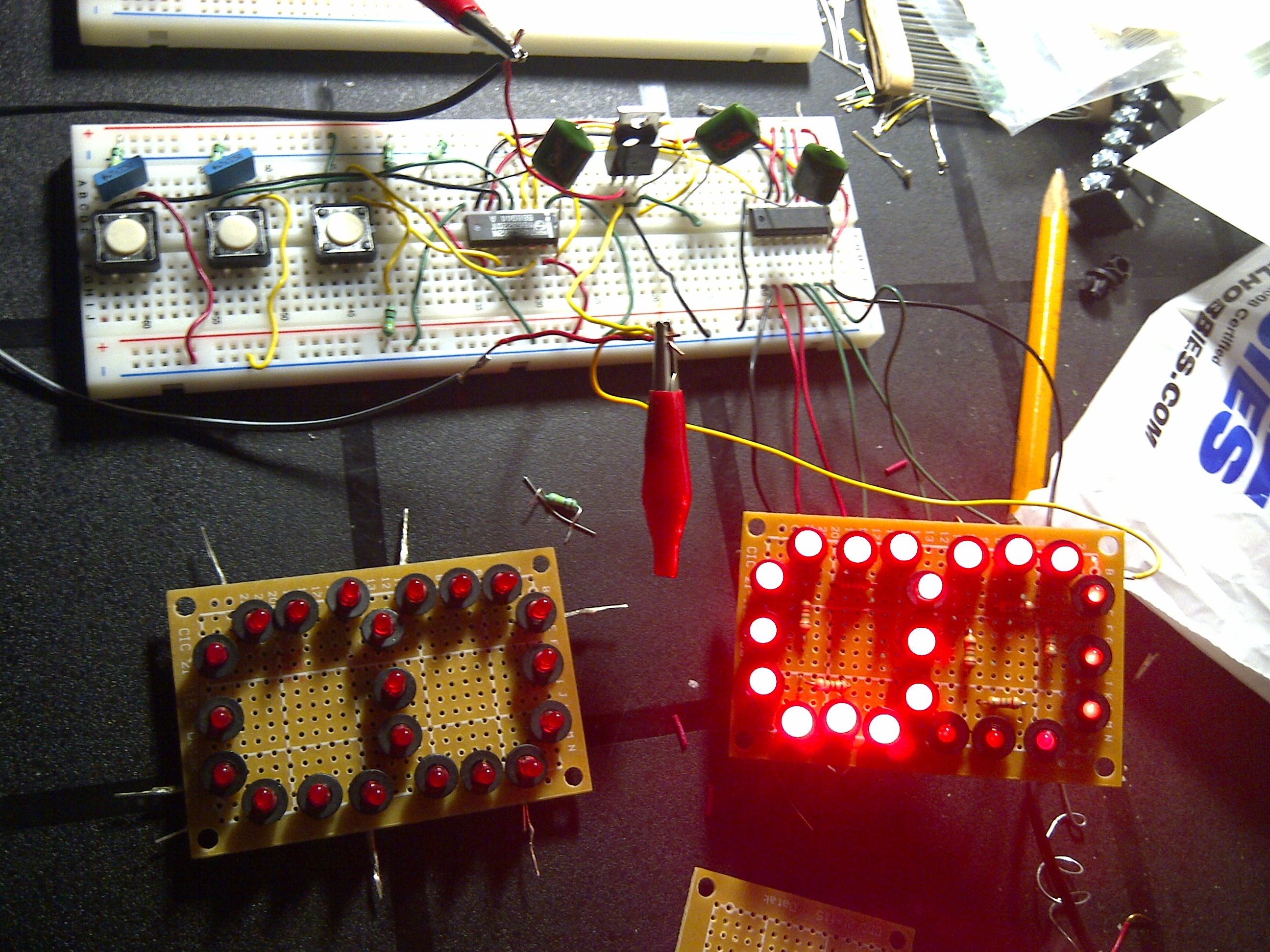
Yes, you can start testing only one digit.
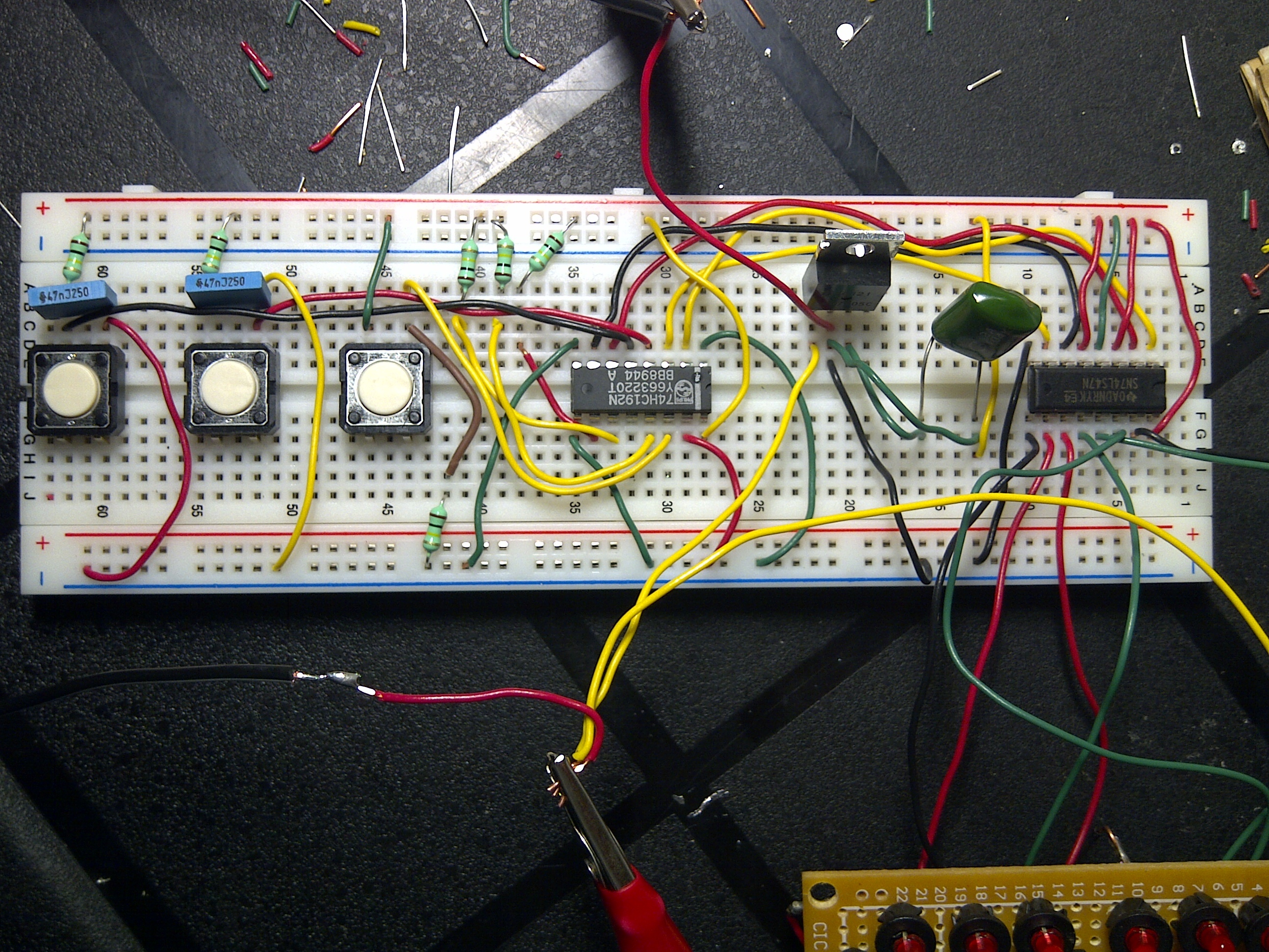
To use 47uF capacitors for C1/C2? No way, you may use 47nF (any value between 22nF and 100nF).
47uF = 47.000.000 pF
47nF = 47.000 pF
 

Hi mister_rf

Just came from a two days vacation, I was excited to test the project did not realize I still had the 47uF on it on the C1 and C2. Do you know if this affected the IC's and not make them work anymore?

Please advise.. Thanks a lot.
 

Parallel capacitors value on each push button are not so critical in some range, but normally we are using smaller values for (47nF-220nF). A such large capacitor limit the ability to press quickly the buttons.
 

mister_rf

So, you're saying even if I accidentally tested the one digit project from a 9V power supply using the 47uF capacitors on C1 and C2 did not affect the IC's (counter and decoder). I'm afraid it may have affected it and not be able to use it anymore.

Please let me know.
Thanks..
 

Theoretically the large value of the capacitor do not create problems, practically at maximum charged may be accidentally discharged in the circuit, so it's difficult now to tell what’s the situation there.
Try again without the capacitors and see the results.
 

mister_rf

First, I'll try taking out the capacitors at C1/C2 and see if it works. Otherwise, I will change the 47uF to 22nF-100nF and I will let you know tomorrow.

Thanks a lot again for all your help.
 

mister_rf

I was really disappointed with the project that i wasn't able to work it right. Even if I did disconnected the large value capacitor C1\C2 on the switches. Also, how can I properly connect the 4 pin tactile switches? should I easily connect 1 pin for the + and 1 pin opposite for the GND? Looks like the IC's has been affected by the large volume charge ton it when I first tested it. Should I just remove these IC's and replace it with new ones? How will I know its not working anymore?

If I can't get it working? Is there any other circuit that I can apply using the same - 74HC192 and 74LS47? I followed the pin connections the best I can, what is the pin connection to pin 3,4,5 on the 74LS47? on your diagram, it says H on it.

Please advise.

thanks so much again.
 

Have you connected the power supply for the circuits? :-D
 

Attachments

  • Counter details 74LS192.GIF
    Counter details 74LS192.GIF
    81.8 KB · Views: 117

mister_rf

Yes, I did connected the power supply. I've also connected the positive on the pin-1 (input) of teh voltage regulator and the negative on the common.

---------- Post added at 16:04 ---------- Previous post was at 15:58 ----------

mister_rf

OK, I see you have the diagram showing that the connections to all the pin 16's (i didn't connect it). It's probably why. OK, I'll try connecting it again and I'll let you know.

Thanks so much again.
 

See all details here:
 

Attachments

  • Counter details 74LS192.JPG
    Counter details 74LS192.JPG
    262.1 KB · Views: 130

mister_rf

Unfortunately, I couldn't make it work.

Here's what I have done;

- I was able to test my 7 segments by itself connecting 150ohms per segment using the 9V power supply.
- then, I connected teh segments to my 74LS47 and I followed the correct pinouts.
- I used 47 nF cap now on C1 and C2 and followed your connections on the detailed diagram.
- this time I connected all the 16's pins on the +V and 8's on teh GND.

Question:
- how come you have a blue coded color line and a black color lines on your GND's connections? I would imagine just to distinguish a negative and a GND line correct?
- are there any difference between 4 pin tact push switches? anyways, I used 47nF I thing it's (250V - 100ma) this time on my C1/C2. Is the 250V matters?

- the connection on the +V and the GND between the digits on the diagram, where should the GND connected to? or that should relpaced your L7805 circuit?

OVERALL, there seem to be NO power continuity between each IC's to the switches...

Please advise and I will try it again tonight. I will send you some images later on what my connections is...


Regards,

barbaro

---------- Post added at 11:41 ---------- Previous post was at 10:29 ----------

mister_rf

Pls check out my connections...


Forget about colors… :grin: Black and blue was just an idea for the GND wires.

Now you need to change some connections.
First you need to connect the LM7805 output to the +5V line.
Also one of the push buttons need to be rewired. See the details attached.
 

Attachments

  • some changes.JPG
    some changes.JPG
    734.1 KB · Views: 95

The capacitor need to be placed close LM7805 circuit, so the connection inductance will be minimized.
 

Attachments

  • capacitor 1.jpg
    capacitor 1.jpg
    167.2 KB · Views: 63
  • capacitor 2.jpg
    capacitor 2.jpg
    240 KB · Views: 60

mister_rf

Thanks so much for reviewing my circuits.

I'm really glad that I have only minor changes. So, I'll make shure to do the following as per your corrections.

- make sure to place the capacitor closer to the voltage regulator LM7805.
- move the connection from pin 4 of the 74HC192 to the opposite leg of the 47nF capacitor on B2.
- move the connection from the +V (yellow line) to the other leg of the capacitor connected to the voltage regulator LM7805.

Yes, the (red line) connected to the allgtr clip is the power supply GND.

With this changes, I'm really hoping to make it work tonight.

Thanks so much again.

Did you see any connections that is out of the ordinary? Please let me know. Thanks.
 

mister_rf

Finally get it working, after made the minor connection changes. The only issue I'm having now is that it doesn't count more than 3 or more and always defaulted to seven or 8 even if I push the clear button B3.

As well, it looks like the function of the B2 and B3 are similar - it counts 6 and then 7 - 8, it doesn't go beyond number 8 or should start from 1.

Attached is the thumbnail, could you please review the connections and let me know if there are anymore modification I should make or is it because I haven't connected the other "tens" digit circuit yet.


Please advise. Thanks so much


Barbaro.
 

First need to check again some connections between 74HC192 and 74LS47.
 

Attachments

  • test again.jpg
    test again.jpg
    320.1 KB · Views: 86

mister_rf

I'll double check those connections and will let you know. It seems that it's just minor. Maybe the connections are loose? or could be not making any good contact?

If there's a need, should I try to interchange the connections? Looks like those are the ABCD input-putput circuits.

Thanks,

Barbaro
 

I suppose it’s only a loose wire, maybe the wire diameter over the limit for this breadboard…
 

mister_rf

Thanks so much again. Yes, I will double check these connections for loose wires.
 

Again a minimum connections list.
 

Attachments

  • short diagram.JPG
    short diagram.JPG
    55.9 KB · Views: 91

Status
Not open for further replies.

Part and Inventory Search

Welcome to EDABoard.com

Sponsor

Back
Top