shirotpoison
Newbie level 6
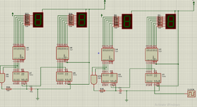
so i have 2 counters for seconds an 2 counters for munits the problem is how to connect the second block with the munits block ,when i add a AND gate it glitched the munits counter hits 1 on 40 second , i add an RC circuit it make seconds reech 60 but the munits steel go 1 on 40 seconds , So any solution of how to connects the two blocks together correctly