Continue to Site

Welcome to EDAboard.com

Welcome to our site! EDAboard.com is an international Electronics Discussion Forum focused on EDA software, circuits, schematics, books, theory, papers, asic, pld, 8051, DSP, Network, RF, Analog Design, PCB, Service Manuals... and a whole lot more! To participate you need to register. Registration is free. Click here to register now.

Need an OP-AMP of Low power consumption for a active low pass filter application

Status
Not open for further replies.
the pulse signal is AC from which the heartbeat rate is extracted.
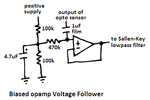
So, if the Sallen-Key filter is used then a bias voltage should be applied, lets say for example if the supply voltage is 3V then the bias voltage needed is 1.5V Isn't it.
Yes.

How will it differ with the single and dual polarity supplies.
With a single-polarity +3V supply, the bias voltage is +1.5V then the output can swing almost +1.5V up to almost +3V and the output can swing almost 1.5V down to almost ground.

With a positive 1.5V and negative 1.5V dual-polarity supply, the bias voltage is 0V then the output can swing almost +1.5V and swing almost -1.5V.
 

But the V(in) for the sallen key filter is the signal as shown in the image of previous post.So, where the bias voltage should be applied ?
 
Last edited:

Hello, The practical implementation of sallen key low pass filter by feeding the phototransistor output with the combinations of
1) resisitors of 24K and both capacitor of 10uf ( as mentioned in the post10 )
2)resistors of 10k and both capacitors of 10 uF(combination generated from this sallenkey lowpass filter design **broken link removed** ) and
3)with the feedback capacitor double of the ground capacitor( as mentioned in the post14 ) everything resulted in the almost no pulse.But the same output of phototransistor when implemented with the first stage of signal conditioning as here https://embedded-lab.com/blog/?p=5508gave the pulse similar to the pulse shown in the above link ( in the second figure of oscillscope figure).
Any suggestions for the circuit to get the pulse using the sallen key lowpass filter(which is used to replace the two LPF filters used in the actual design).
 

But the V(in) for the sallen key filter is the signal as shown in the image of previous post.So, where the bias voltage should be applied ?
Look at my reply #10. A Sallen-key lowpass filter must be driven from a low impedance like the output of another opamp. This new opamp can have its input biased at half the supply voltage, have a gain of 1 like a follower and its output can be DC-coupled to the Sallen-Key lowpass filter circuit.

Hello, The practical implementation of sallen key low pass filter..... resulted in the almost no pulse.
Because the opamp in the Sallen-Key filter had no bias voltage!

For a heartbeat waveform, the filter type does not matter. Use the two simple filters in the link if you want, but they must also be biased.
 

The opamp input needs to be biased and also needs the phototransistor output.I am unable to get this point.If possible can you give a pictorial view of first opamp circuit for biasing the sallen key LPfilter.
 

Here is an opamp voltage follower with a gain of 1.
It has a high input impedance and a low output impedance.
 

Attachments

  • opamp voltage follower.png
    opamp voltage follower.png
    13.7 KB · Views: 57

The OPA381 IS NOT AN OPAMP, it is a transimpedance amplifier so it cannot be used in your filter circuit.
Your filter is as droopy Bessel instead of a sharp Butterworth type.
 
Thanks Audioguru for making me to realize that the OPA381(TAI) cannot do this job.I don't know that the TAI cannot replace the normal OPAMP I was just struggling by using a OPA381TAI.Will the replacement of OPA381 with MCP6001(used in the original design) for the sallenkey butterworth type of filtering efficient filtering as compared to the two simple filters used in the embeddeddesign.
 

Thanks Audioguru for making me to realize that the OPA381(TAI) cannot do this job.I don't know that the TAI cannot replace the normal OPAMP
I told you a few times.

Will the replacement of OPA381 with MCP6001(used in the original design) for the sallenkey butterworth type of filtering efficient filtering as compared to the two simple filters used in the embeddeddesign.
The MCP6001 produces plenty of noise at low frequencies. You will need to change the values in your filter for it to be Butterworth.
 

@Audioguru:I used the equal resistor values of 24K and capacitors as 10uF as mentioned here https://www.edaboard.com/threads/301340/ that " A Sallen-key lowpass filter oscillates if its gain is more than 3. It has a Butterworth response if the resistor values are the same, the capacitor values are the same and its gain is about 1.6 times."
Can you suggest me the changes need to be made to make the sallen key filter with 24k and 10uF to a butterworth one.If possible about increasing the gain also.
Thanks.
 

Thanks Audioguru for making me to realize that the OPA381(TAI) cannot do this job.I don't know that the TAI cannot replace the normal OPAMP I was just struggling by using a OPA381TAI.Will the replacement of OPA381 with MCP6001(used in the original design) for the sallenkey butterworth type of filtering efficient filtering as compared to the two simple filters used in the embeddeddesign.

Who has told you that the OPA381 couldn`t be used as a positive fixed gain amplifier? Of course, it can!
There is only one single (minor) restriction you have to fulfill: The feedback gain-determining resistor must be larger than a minimum value given by the manufacturer.
If you intend to use equal componenets in the frequency-determining network (R1=R2=R and C1=C2=C) the cut-off frequency is at w,c=1/RC and the required non-inverting gain is (3-1/Qp).
Qp is the pole quality factor - and for Butterworth response: Qp=0.707

EDIT: Be aware that this equal-component design is rather problematic because the filter response (Butterworth characteristic) is very sensitive to gain variations.
That means that you must try to meet the required gain of +1.5858 as exact as possible.
Therefore, in many cases another approach is used: Design for a gain of +2, which can easily be met with two equal resistors as feedback elements.
In case you are interested, I can give you the corresponding formulas for R1, R2, C1 and C2.
 
Last edited:

@LVM:Hello,I am interested in implementing the OPA381TIA in the sallenkey lowpass if it can effectively filter and better than the Active LP filter with MCP6001 as mentioned in the https://embedded-lab.com/blog/?p=5508 as its mentioned in so many posts in this thread that the active LP filter implemented is not effectively filtering.
Yes, I need the calculation and corresponding formulae for the LP filter design(sallenkey LPfilter) with OPA381TIA.
Thanks.
 

I am interested in implementing the OPA381TIA in the sallenkey lowpass if it can effectively filter and better than the Active LP filter with MCP6001 as mentioned in the https://embedded-lab.com/blog/?p=5508 as its mentioned in so many posts in this thread that the active LP filter implemented is not effectively filtering.
Yes, I need the calculation and corresponding formulae for the LP filter design(sallenkey LPfilter) with OPA381TIA.
The blog uses two extremely simple filters. A Sallen-Key Butterworth filter is much better.

I don't think you hear me: The OPA381 is a transimpedance amplifier but a Sallen-Key Butterworth filter is made with an opamp which is completely different.

A Sallen-Key Butterworth lowpass filter can use equal value resistors and capacitors and a gain almost 1.6, or it can have a gain of 1 and equal-value resistors and the feedback capacitor value should be double the value of the capacitor to ground.
 

I don't think you hear me: The OPA381 is a transimpedance amplifier but a Sallen-Key Butterworth filter is made with an opamp which is completely different.
A Sallen-Key Butterworth lowpass filter can use equal value resistors and capacitors and a gain almost 1.6, or it can have a gain of 1 and equal-value resistors and the feedback capacitor value should be double the value of the capacitor to ground.

Hello audioguru - I am afraid, you are confusing the questioner.
1.) Please, can you give any reason why a transimpedance amplifier shouldn`t be used as a non-inverting gain stage? It is not sufficient just to state "it cannot be used" (see your post#28) without any justification.
Application of fixed-gain amplifiers is one of the classical usage of these integrated devices. Why? Because they exhibit very large slew rate capabilities if compared with "classical" opamps.

2.) More than that, please note that there are various design strategies for realizing Sallen-Key filters. "Sallen-Key" means only: Fixed gain - nothing else. This gain can be even negative!
You can use equal parts values resulting in certain gain requirements or you can fix the gain and use other parts values.
One disadvantage of all Sallen-Key filters is that they are rather sensitive to parts tolerances - in particular tolerances of the gain-determining resistors.
For this reason, one of the best alternatives is to use a gain-of-two dimensioning (2 equal valued resistors in the feedback path).
Of course, you also can use unity gain configuration which offers, of course, the most exact gain value (100% feedback).

3,) Final and general remark: Filter design is one of the most challenging task in analog electronics because you have to select a circuit realization out of many alternative topologies and design strategies.
Under IDEAL conditions (ideal amplifiers and no parts tolerances) all alternatives lead to the same transfer function. Differences can only be seen under real conditions because all versions behave differently when they are faced to non-ideal opamp properties and tolerances of passive parts.

- - - Updated - - -

Yes, I need the calculation and corresponding formulae for the LP filter design(sallenkey LPfilter) with OPA381TIA.

For my opinion, you should choose on of the following two realizations: Unity gain (as mentioned already by audioguru in his last post) or a gain of two.
* Unity gain: w,c=1/(R*C2*sqrt(2)) with two equal resistors R1=R2=R and C1=2*C2 (C2 grounded).
* Gain of "2": w,c=1/(R1*C*sqrt(2)) with two equal capacitors C1=C2=C and R2=2*R1 (R1 connected to signal input).

Comment: The second alternative (gain of two) has the advantage of two equal valued capacitors (better than C1=2*C2 as in the unity gain case).

- - - Updated - - -

Hi patan.gova,

there is one thing I forgot to mention:
When using a transimpedance amplifier in unity-gain application you connect the output with the inverting input without using a resistive voltage divider (as it is the case for each opamp) - however, here you must insert a resistor between output and inv. input of several kohms. This is to limit the CURRENT into the low-resistive input terminal. The minimum value of such a resistor is specified by the manufacturer (data sheet)
 
Last edited:
This project measures very low frequency heartbeats so the very high slew rate from a transimpedance amplifier trying to be used as a low frequency lowpass filter is not needed and is not wanted.

The gain-setting resistors for an "equal values" Sallen-Key Butterworth filter can be ordinary 5% tolerance because the accuracy of the amount of peaking (if any) of the filter does not matter. The same applies to the tolerance of the capacitors.
The original circuit didn't even use a sharp Butterworth filter. Instead it used a "droopy" filter.
 
Of course active filters can be implemented with transimpedance amplifiers. It's generally possible in Sallen-Key topology, if the feedback resistor requirements are fulfilled. The problem is that the OP always selected circuits that aren't suitable for TIAs because they had been designed for regular voltage OPs. I also didn't hear a understandable reason why a transimpedance amplifier should be used for a filter with low Hz bandwidth.

As the OP has obviously only little knowledge of analog circuit design, it seems reasonable that Edaboard members suggest a standard OP filter circuit for the application.
 

The transimpedance amplifier is a photo-diode preamp on its datasheet which might be why the OP wants to use it (except he connected his photo-diode upside-down). But now I think he is using a photo-transistor instead, then the transimpedance amplifier is not needed.
 
This project measures very low frequency heartbeats so the very high slew rate from a transimpedance amplifier trying to be used as a low frequency lowpass filter is not needed and is not wanted.

Yes - this sounds reasonable (in contrast to "The OPA381 IS NOT AN OPAMP, it is a transimpedance amplifier so it cannot be used in your filter circuit.")
 

ThankaLot Audioguru.
Now, I am perfectly switching to the usage of normal OPAMP in place of OPA381TIA. The attachment below shows the available OPAMP with me but I am confused which to use.
Can you please suggest one from the list which will do the job same( or similar) to the MCP6001 so that I can start using it.
Thanks.
 

Attachments

  • OPAMPS.pdf
    96 KB · Views: 61

Status
Not open for further replies.

Similar threads

Part and Inventory Search

Welcome to EDABoard.com

Sponsor

Back
Top