Continue to Site

Welcome to EDAboard.com

Welcome to our site! EDAboard.com is an international Electronics Discussion Forum focused on EDA software, circuits, schematics, books, theory, papers, asic, pld, 8051, DSP, Network, RF, Analog Design, PCB, Service Manuals... and a whole lot more! To participate you need to register. Registration is free. Click here to register now.

Need an OP-AMP of Low power consumption for a active low pass filter application

Status
Not open for further replies.

patan.gova

Full Member level 3
Joined
Dec 19, 2011
Messages
172
Helped
4
Reputation
8
Reaction score
0
Trophy points
1,296
Activity points
2,776
Hello,
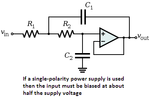
I am working to filter out the high frequency components above 2.3Hz using an active lowpass filter which consists of a OPA380 OP-AMP and to provide a gain of 101 as shown with in the attached image.I practically checked and everything working fine but the OP-AMP is consuming a current of 4ma when provided with a 3V voltage supply.
I will be feeding the active lowpass filter with a signal of 8mv and I need to amplify this signal for further reading of microcontroller's ADC while filtering the above mentioned frequency.
Can someone suggest
1.A Lower current consumption Op-amp and the gain should also be good.
2.what will be the maximum gain that should be used by an op-amp.
OPAMP circuit.png
 
Last edited:

The circuit isn't exactly a low pass, it's a first order pole-zero combination (lag-lead).

For the OP selection, every major manufacturer has internet selection tools. Just enter your preferred combination of parameters.
 

So, Can I know how to design a active lowpass filter with a cutoff frequency of 2.3Hz with a gain of 100.
 
Last edited:

I guess you did not look at the datasheet for the OPA380. It IS NOT an opamp. It is a high frequency, high quiescent current transimpedance amplifier that is usually used as an inverting amplifier that has a photodiode as its input.

An active lowpass filter is simple but first you must decide its order. An order of only one reduces high frequencies only 6dB (half the level) per octave. An order of two reduces high frequencies 12dB per octave. An order of three reduces high frequencies 18dB per octave etc.

You also must decide if you want a Butterworth response or another type of response. A Sallen and Key Butterworth second-order lowpass filter might be what you need and Google shows how to make it.

Some low power opamps produce crossover distortion, like an LM358 dual or an LM324 quad.
 

Hello Audioguru,
I am implementing the pulse sensor to calculate the heartrate by following the circuit shown in this link https://embedded-lab.com/blog/?p=5508.As the frequencies needed to filter will be same as shown in this link except the OP-AMP which is consuming 4ma and used only first stage of filtration. So, I am wondering whether can I get an OP-AMP consuming lower current and which does the same job as shown in the implementation. But I haven't tried MCP6004 that was used in this.
As I want to know more about the low power consuming and providing a good gain OPAMP before ordering an OP-AMP and need some suggestions to design active lowpass fitler for this application like what should be the order ,type etc.
 
Last edited:

The OPA380 transimpedance amplifier IC is completely different to the MCP6004 quad opamp.
The circuit was designed for the MCP6004 rail-to-rail low power opamp that does not need a bias voltage so why not use it??
The quiescent current for the MCP6004 is typically only 0.1mA per amplifier.

The circuits use two single-order lowpass filters (they are not active filters) that reduce high frequencies a total of 12dB (one-quarter of the level) per octave.
A single opamp can be used instead to make a second-order Sallen and Key Butterworth active filter.

The circuits are missing a very important supply bypass capacitor that prevents the opamps from oscillating.
 

Thanks for the information,as this MCP6004 is using a quiescent current of 0.1 ma so this can be used for my application.
But in their website they have mentioned it as a active LP filter.Can you please explain how to design only one OP-AMP for the second-order Sallen and Key Butterworth active filter and will they do the same job as the two single-order lowpass filters as used in the design (shown in the above link).If so it will reduce the size of the circuit I guess.
 

The very simple passive single-order lowpass filter is simply a resistor and capacitor buffered by an opamp. Its opamp is non-inverting so the filter response is poor, it should be inverting. The design is not good.

A second-order Sallen and Key Butterworth lowpass active filter uses positive feedback from its opamp to make its response very sharp. Its opamp is non-inverting.

EDIT: Look in Google for Sallen-Key lowpass filters.
 

Attachments

  • Sallen-Key lowpass active filter.png
    Sallen-Key lowpass active filter.png
    9.7 KB · Views: 100
Last edited:

Thanks and I just gave a hit with this providing the cutoff frequency of 2.3Hz **broken link removed**.
But will this Sallen-Key Low-pass Filter will yield the same result as using two single-order lowpass filters as used in the designhttps://embedded-lab.com/blog/?p=5508.Also in the design each LPfilter provided a gain of 100 making overall system gain as 200 around but the sallen key LP filter gain is 1.How to amplify the signal then.
 
Last edited:

Your two single-order lowpass filters produce a droopy Bessel response because there is no positive feedback to boost the response at the cutoff frequency.
It is droopy because it reduces some of the frequencies that you want to pass.

The Sallen-Key lowpass filter is designed for a Butterworth response so its response is sharp at the cutoff frequency. Also it needs only a single opamp.

Your link to the Sallen-Key Butterworth lowpass filter with 30k and 18k resistors is usually done with equal-value resistors of 24k. I simulated them and they both have exactly the same frequency response.
The Sallen-Key filter needs to be driven by a low resistance (an opamp) that can have a gain of whatever you want. This input opamp needs biasing so that the entire waveform is amplified, not just the positive side of it.
 

Just a short comment, the shown single OP Sallen-Key low-pass filter can be implemented with additional gain, it can realize different filter charactecristics from bessel to chebyshev, and it can be extended to third order if required. Most engineers use a filter design toll for ease of calculation.

Pulling the gain into the filter is only feasible with sufficient OP loop gain which is often a problem for higher filter cut-off frequencies. But it can perfectly work for 2.3 Hz. Alternatively you can separate gain and filter function and refer to a micropower OP with respective low bandwidth.
 

Your two single-order lowpass filters produce a droopy Bessel response because there is no positive feedback to boost the response at the cutoff frequency.
The Sallen-Key lowpass filter is designed for a Butterworth response so its response is sharp at the cutoff frequency.
.

Hi audioguru - just a short correction and a comment::
A second-order Bessel response has a pole Q of Op=0.577. In contrast, a cascade of two single-pole low pass circuits has, of course, two real poles. Thus, the selectivity of a real Besel response is better than of two single-pole filters.
More than that, a short look onto the graph of a Butterworth response reveals that the transition from the pass band to stop band cannot be described as "sharp".
It is a response that also is called "maximally flat" - that´s all. That means: It has no peaking effect like all Chebyshev responses.
 

So I am confirmed that I can use this Sallen-Key low-pass filter to replace the two single-order lowpass filters for a cutoff frequency of 2.3Hz.
@Audioguru:I read about biasing on this but quite confused because there are so many methods for applying.So how to apply bias for my application for an input signal of this Pulse_signal.JPG and how to analyse it.
@FVM:How to make the gain calculations and how much gain is needed for the mentioned Sallen-Key low-pass filter so as to make the above shown input signal to be amplified to feed to the ADC of the microcontroller.
 

A Sallen-key lowpass filter oscillates if its gain is more than 3. It has a Butterworth response if the resistor values are the same, the capacitor values are the same and its gain is about 1.6 times. It also has a Butterworth response if the resistor values are the same, the feedback capacitor value is double the value of the capacitor to ground and the gain is 1 times.

Use the simple filters if you want to blink an LED or have a square-wave output.
Use a Sallen-Key filter and bias the opamps if you want a proper waveform output (as shown in your last attachment).

The first circuit has no bias voltage for the opamps so their outputs can go only positive. The negative swing of the waveform is missing.
A biased opamp has an output that can swing positive and swing negative so it reproduces the entire waveform.
 
Last edited:

As mentioned above "Use a Sallen-Key filter and bias the opamps if you want a proper waveform output (as shown in your last attachment)." Can I get more information on this
1.what should be the gain needed to amplify the signal shown here Pulse_signal.JPG so that it can be feeded to the ADC of the microcontroller.
2.Need more information on how much bias should be provided( also how to know it) to amplify the above shown image.How the circuit looks like.
3.If anything more needed.
 
Last edited:

A Sallen-key lowpass filter oscillates if its gain is more than 3.
True for equal R + equal C which is just a special case of the various possible Sallen-Key implementations. As mentioned in post #11, you can implement arbitrary filter characteristics and any gain >= 1 by selecting different R and C values.
 

Anything about the biasing of op-amp like what should be the needed bias voltage and where to provide it and how to analyse its affect.
 

The required DC bias is an unclear point. A low-pass, as requested in the initial post would copy the DC level of the input signal and amplify it by the gain factor. Or you explicitely specify a DC offset, which hasn't been done yet.

I assume that the output signal should be centered around 2.5 V, but how about the input signal DC level?
 

The opamps in the first circuit posted have no DC bias. 0V is the quiescent voltage and the output is simply a positive pulse, completely different to a heartbeat waveform that is AC and has a negative portion.

If a Sallen-Key filter is used then it must have a bias voltage so that its input and output can swing positive and negative around the bias voltage which is usually at half the supply voltage. Or a dual polarity supply can be used and the bias voltage will be 0V which will be half the total supply voltage.
 

@audioguru:Yes you are right the pulse signal is AC from which the heartbeat rate is extarcted.
So, if the Sallen-Key filter is used then a bias voltage should be applied, lets say for example if the supply voltage is 3V then the bias voltage needed is 1.5V Isn't it.
How will it differ with the single and dual polarity supplies.
 

Status
Not open for further replies.

Similar threads

Part and Inventory Search

Welcome to EDABoard.com

Sponsor

Back
Top