Continue to Site

Welcome to EDAboard.com

Welcome to our site! EDAboard.com is an international Electronics Discussion Forum focused on EDA software, circuits, schematics, books, theory, papers, asic, pld, 8051, DSP, Network, RF, Analog Design, PCB, Service Manuals... and a whole lot more! To participate you need to register. Registration is free. Click here to register now.

Need an OP-AMP of Low power consumption for a active low pass filter application

Status
Not open for further replies.
The attachment below show the available OPAMP with me but I am confused which to use.
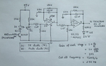
I guess you did not look at the list you posted because some are not opamps, instead they are instrumentation amplifiers. Some use a high supply current and some are noisy. The OP484 is a suitable but it is very expensive.
 
@audioguru:I used OP484(as you advised) in place of the MCP6004 with a supply voltage of 3V and implemented the first stage of embedded lab with the phototransistor and Green LED and the output obtained was quite good as shown here **broken link removed**
But I am confused with this
1)The output pulse is having a DC component which should actually be removed by the Capacitor in the Highpass stage but don't know why it is still there.
2)The output pulse is of 200mV which is obtained by using a gain of 101 can I use gain of 101 for this OP484?

I am planning to implement the sallenkey LP filter as you mentioned that a single stage of the sallenkey LP filter will replace the two stage LP filters and will effectively filter the output compared to the simple filters used in the embedded lab blog.
Also "LvM" mentioned that compoents needed for sallenkey LPfilter implementation with different gain as
* Unity gain: w,c=1/(R*C2*sqrt(2)) with two equal resistors R1=R2=R and C1=2*C2 (C2 grounded).
* Gain of "2": w,c=1/(R1*C*sqrt(2)) with two equal capacitors C1=C2=C and R2=2*R1 (R1 connected to signal input).
But if the sallenkey LP filter is made with a gain of 1 or 2 then that won't make the pulse signal to be sufficient to read by the microcontroller as I need the pulse signal to be atleast 1V to read by the microcontroller.
Can you explain soemthing about the gain for the output pulse if sallenkey LPfilter is used.
Thanks.
 

Why did you use a green LED? Do you have green blood and green skin?
Most of these circuits use a red LED or an IR LED and IR photo-diode.

Your 200mV pulse has a low amplitude. You need more gain.
Your 'scope photo does not have 0VDC marked so I cannot measure DC voltages.

A couple of minutes ago I answered a thread similar to this one. Do you have the same thread on another website?
Oh, the other thread about THIS SAME CIRCUIT is on THIS WEBSITE and is here:
 

1)Why did you use a green LED? Do you have green blood and green skin?
Because most biological tissue has lower scattering and absorption coefficients for red and near-infrared light. This makes them very useful for measuring the transmission of light in tissue.Their low scattering property also means less backscattering for taking reflectance measurement. In order to acquire a good
reflectance photoplethysmograph signal, blue and green light are more preferable.So,I used green LED.
2)Your 200mV pulse has a low amplitude. You need more gain.
Can explain something about increasing the gian as the sallenkeyLP filter will only give a max of 2 as mentione in post#42.How to increase signal gain if sallenkey LP filter is used.
Your 'scope photo does not have 0VDC marked so I cannot measure DC voltages.
I guess the cursor at position2 indicates the 0vDC mark.
3)A couple of minutes ago I answered a thread similar to this one. Do you have the same thread on another website?
No,I only have a thread in this website and I guess may be i was editing the post when you answered the first in the mean while.
 
Last edited:

The gain of your ... WAIT A MINUTE. Which thread is this? One of your threads has a transimpedance amplifier with unknown gain that doesn't work and the other thread uses an opamp with a gain of only 101 times.

A heartbeat project I posted in your other thread uses an IR LED and has a gain of 10,000 times. It is this circuit:
 

Attachments

  • hearbeat circuit.png
    hearbeat circuit.png
    219.4 KB · Views: 67

Yes,I knew this and it is the 1st version of the one which I was posting all these days.I was implementing the same but with a TIA opamp instead of opamp and after you informed that a TIA op amp cannot be used in place of opamp, then realised and started using the OP484(the one currently working with).
And also after you informed me that the two stages of active lowpass filters in this blog can be replaced by a singel sallenkey LP filter which will effectively filters so I was planning to implement and was asking you about the increasing the gain if the sallenkey LP filter is used.
 
Last edited:

Two opamps will make the gain of 10,000 and a third opamp can be a Sallen-Key Butterworth lowpass filter with a gain of 1. You might also need a Sallen-Key Butterworth highpass filter with a gain of 1 made with a fourth opamp.
 

@audioguru:I want to reduce the size of the circuit or the number of components being used.Also the Power consumption.
Is there a way of making a effective filter by using sallenkey bandpass filter or any other and a stage to increase the gain so that the signal of say 20mV to around 1V because using the above mentioned process will need more components I guess.
I really need to reduce the size of the circuit and also power consumption with effective filtering.
And I will replace the analog filters(if needed) with digital filters in micro controllers while using only the mandatory analog part.
 
Last edited:

20 mV to 1V means gain of 50 and is well possible as additional filter gain, also 100 or 200. Previously discussed gain of 10000 won't be a good idea for single stage.

I presume you are able to operate any of the free filter tools like TI FilterPro to get the filter calculated.
 

@FvM:Can I use only a sallenkey bandpass filter instead of using a simple high pass + active lowpass filter( as mentioned in the embedded lab blog) for effectively filtering and a with adjustable filtering gain for my requirement.
I am pretty new to this filter design and I just looked the TI filterpro but was not able to find a sallenkey bandpass filter design option.
Can you help me out with the sallenkey bandpass filter.
Thanks.
 
Last edited:

A dual opamp is in an 8-pins case the same size as a single opamp. You need two opamps for the gain of 10,000 as shown in the schematic I found.
I have never heard of a Sallen-Key bandpass filter. Instead you need a sharp lowpass and maybe a sharp highpass. Sallen-Key filters are much sharper with steeper slopes than the simple filters. The frequencies of simple filters overlap and attenuate the frequencies you want.

Many bandpass filters using a single opamp sharply pass only a narrow band of frequencies then the slopes are gradual.

- - - Updated - - -

A Sallen-Key filter is either lowpass or highpass. They are sharp so when you use a lowpass AND a highpass then the bandpass response is flat and the slopes are steep. The frequencies you want are not attenuated like if simple overlapping filters are used.
 
I just looked the TI filterpro but was not able to find a sallenkey bandpass filter design option.


The Sallen-Key bandpass exists and can be selected during the Filterpro design process.

A dual opamp is in an 8-pins case the same size as a single opamp. You need two opamps for the gain of 10,000 as shown in the schematic I found.
I have never heard of a Sallen-Key bandpass filter. Instead you need a sharp lowpass and maybe a sharp highpass. Sallen-Key filters are much sharper with steeper slopes than the simple filters. The frequencies of simple filters overlap and attenuate the frequencies you want.

Many bandpass filters using a single opamp sharply pass only a narrow band of frequencies then the slopes are gradual.

- - - Updated - - -

A Sallen-Key filter is either lowpass or highpass. They are sharp so when you use a lowpass AND a highpass then the bandpass response is flat and the slopes are steep. The frequencies you want are not attenuated like if simple overlapping filters are used.

I agree, apart from the Sallen-Key bandpass point. The problem seems to demand for separate high and low pass corners instead of a single center frequency.
 
I designed both the filters sallekey_LP filter with a gain of 50,stopbandfreq=3,2Hz and passbandfreq=3Hz as shown below.
sallekey_HP filter with a gain of 50,stopbandfreq=0,3Hz and passbandfreq=0,5Hz as shown below

sallen_HPF.jpg sallen_LPF.jpg

1)But in the LPfilter design image it showing the cutoff freq=0Hz but the design was made for a cutoff freq=0,5.Can I know why what is the reason for this.
2)Is it possible to use a gain of 50 because here it https://en.wikipedia.org/wiki/Sallen%E2%80%93Key_topology says the gain should be kept less than 3 and also in this https://www.changpuak.ch/electronics/Sallen_Key_Bandpass_light.php design of widebandpass filter it says the filter has unity gain.
3)should I use the unitygainvoltage follower OP-AMP as input to drive the sallenkey HP filter (as "Audioguru" mentioned in post#8) and then giving the output to the sallenkeyLPfilter.
Can explain me a bit on these things.
Thanks.
 
Last edited:

I notice that Filterpro generates erroneous plots for low filter cut-off frequencies. The component values seems to be still correct at first sight.

You may want to enter kHz instead of Hz to get correct curve forms, or use a different tool.
 

Yes,the filter designed in filterpro tool will show the cutoff frequency as 0Hz if cutoff freq needed entered is >1Hz and if fc required is > 1Hz it is showing the correct value after desining the filter.
Can you suggest any other tool for designing and analysing the filters.
 
Last edited:

I wonder if a bandpass filter that has a narrow passband can be used to make heartbeat pulses that might be something like a bongo drum?
 

Status
Not open for further replies.

Similar threads

Part and Inventory Search

Welcome to EDABoard.com

Sponsor

Back
Top