Continue to Site

Welcome to EDAboard.com

Welcome to our site! EDAboard.com is an international Electronics Discussion Forum focused on EDA software, circuits, schematics, books, theory, papers, asic, pld, 8051, DSP, Network, RF, Analog Design, PCB, Service Manuals... and a whole lot more! To participate you need to register. Registration is free. Click here to register now.

[SOLVED] Isolated voltage measurement for low voltage range.

Status
Not open for further replies.

Asilver

Newbie level 4
Joined
Apr 5, 2024
Messages
7
Helped
0
Reputation
0
Reaction score
0
Trophy points
1
Activity points
49
Hey there,
I am working on designing a modular power supply (AC-DC converter) having multiple DC outputs with isolated grounds with each other. I need to measure the voltages of each output and feed it to the micro controller such that ground remains isolated. I tried looking for some methods but all of them are for high voltages, my outputs are in the range of 5-36V DC.
Please suggest some solution for this.
 

Hi,

having multiple DC outputs
what is "multiple"? 2? 10? 100?

I tried looking for some methods but all of them are for high voltages,
They are for high "isolation voltage" or high "measurement voltage range"?


each output "fixed" voltage or "variable" voltage?

Analog? max error? frequency response?
Digital? accuracy? Resolution? sampling frequency? Interface?

****
There are so many solutions. Nothing new. Done million times. Many solutions in the internet.
Most we can suggest can also be found in the internet.

****
We dont know your requirement.
I´ve done many different types. It could be
* duty_cycle generator --> optocoupler --> PWM_input
* analog isolation amplifiers
* high impedance measurement
* ADC --> SPI --> optocoupler --> microcontroller
* analog optocoupler solutions
* signal transformers
* digital isolators instead of digital optocouplers
* inductive coupling
* ready to buy isolating measurement

****

Klaus
 

I'd start with Analog Devices and look for isolation amplifiers
like in the list above. Range, resolution, BW, isolation voltage
are some selection criteria.

Depending on care-abouts you might prefer to use a wide mux
and one fancy amplifier (no idea about the relative costs but
muxes are easy and precision amplifiers, not). Likely more
compact but needful of some kind of addressing.
 

Hi,


what is "multiple"? 2? 10? 100?


They are for high "isolation voltage" or high "measurement voltage range"?


each output "fixed" voltage or "variable" voltage?

Analog? max error? frequency response?
Digital? accuracy? Resolution? sampling frequency? Interface?

****
There are so many solutions. Nothing new. Done million times. Many solutions in the internet.
Most we can suggest can also be found in the internet.

****
We dont know your requirement.
I´ve done many different types. It could be
* duty_cycle generator --> optocoupler --> PWM_input
* analog isolation amplifiers
* high impedance measurement
* ADC --> SPI --> optocoupler --> microcontroller
* analog optocoupler solutions
* signal transformers
* digital isolators instead of digital optocouplers
* inductive coupling
* ready to buy isolating measurement

****

Klaus
Hello Klaus,
The system have 8 fixed DC outputs (5V x 1, 9V x 2, 15 x 4, 28V x 1) and one variable output (9-36VDC via POT). Different cards are used for the outputs.
required isolation is 1KV.
I need to feed it to a micro controller of 10-bit ADC.
One more thing, I need to provide SNMP protocol for this system, can you help in this.
 

Hi,

good informations.

*****
I´m confused about the "SNMP" protocol.
You need it to transfer the "voltage information" across the isolation barrier?
If YES: explain.
If NO: please start a new thread about the SNMP protocol .. by focussing on the SNMP problem. Let´s focus in this thread about the measurement an isolation problem.
Please clarify.

***
OK: So you need to use the ADC. This means the "isolation solution" needs to be analog.
(it would be helpful why you need to use the ADC .. and not a digital input / interface to your microcontroller)

So focussing on analog:
* using analog optocouplers that are designed for transferring analog signals. Often they include a monitoring receiver on the transmitter side.
* using analog isolation amplifiers
* (magnetic) voltage transducers
.. and still I´mnot sure whether a resistive differential measurement is allowed or not.
I´ve done this mayn times even in industrial environment, even for 2500V RMS voltages. It is a simple, rather accurate, cheap, rugged solution that still is according "isolation regulations". There will be a tiny current across the isolation barrier. But as long as the current is within the regulations - even with a fail of a single device - one is on the safe side. In my example I used (across the isolation barrier) two high voltage (5kV rated) glass isolated resistors in series in a way that even if one of the resistors go short circuit that current is still way below a dangerous level.

****
Without detailed requirements about freqency, accuracy .. and so on ... one can not give detailed answers.
Also we don´t know about other requirements, like: cost, size, development time....

I recommend to do internet search about the analog optocouplers, voltage transducers and isolation amplifiers. .. to see which one suits you most.

Klaus
 

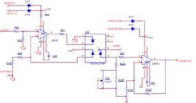
I used isolated optocoupler, along with amplifiers.
 

Attachments

  • isolater.png
    isolater.png
    44 KB · Views: 21

Status
Not open for further replies.

Similar threads

Part and Inventory Search

Welcome to EDABoard.com

Sponsor

Back
Top