Continue to Site

Welcome to EDAboard.com

Welcome to our site! EDAboard.com is an international Electronics Discussion Forum focused on EDA software, circuits, schematics, books, theory, papers, asic, pld, 8051, DSP, Network, RF, Analog Design, PCB, Service Manuals... and a whole lot more! To participate you need to register. Registration is free. Click here to register now.

[SOLVED] [Moved] How bad is my damaged Atlys FPGA board?

Status
Not open for further replies.

Elektronman

Member level 5
Joined
Jun 24, 2011
Messages
89
Helped
1
Reputation
2
Reaction score
1
Trophy points
1,288
Activity points
2,116
Hello,
I've decided to post a picture of the accident which occurred some days ago: I have already talked about it in the thread:
https://www.edaboard.com/threads/226859/

Basically, I bought this Atlys board, and while trying to put it in a small plastic case, I accidentaly teared off :cry: the USB ADEPT port used to configure the FPGA...
while trying to repair it myself... I ended up messing even more the USB port.
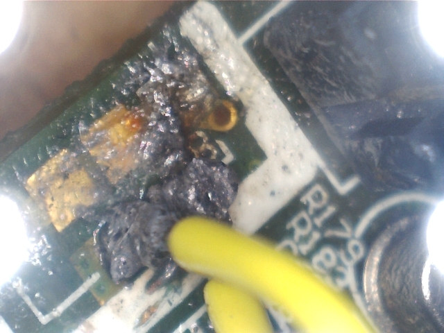
I have attached the picture, where you can easily see the damaged port...
The worst problem is that the USB D- signal pad is disconnected from the track.. and I have no idea how to reconnect those part by soldering... I lack any precision tool able to do something like that.. I tried with my soldering iron but the tip was too wide...

The D+ pad also has a via on the other side of the PCB that connect with the track that goes into the Cypress MCU at pin 8 (D_P), in the picture you don't see this via and you have a misperception of D+ and D- swapped.. but that's not true, it is just an optical illusion...

Unfortunately I have no warranty for this board...

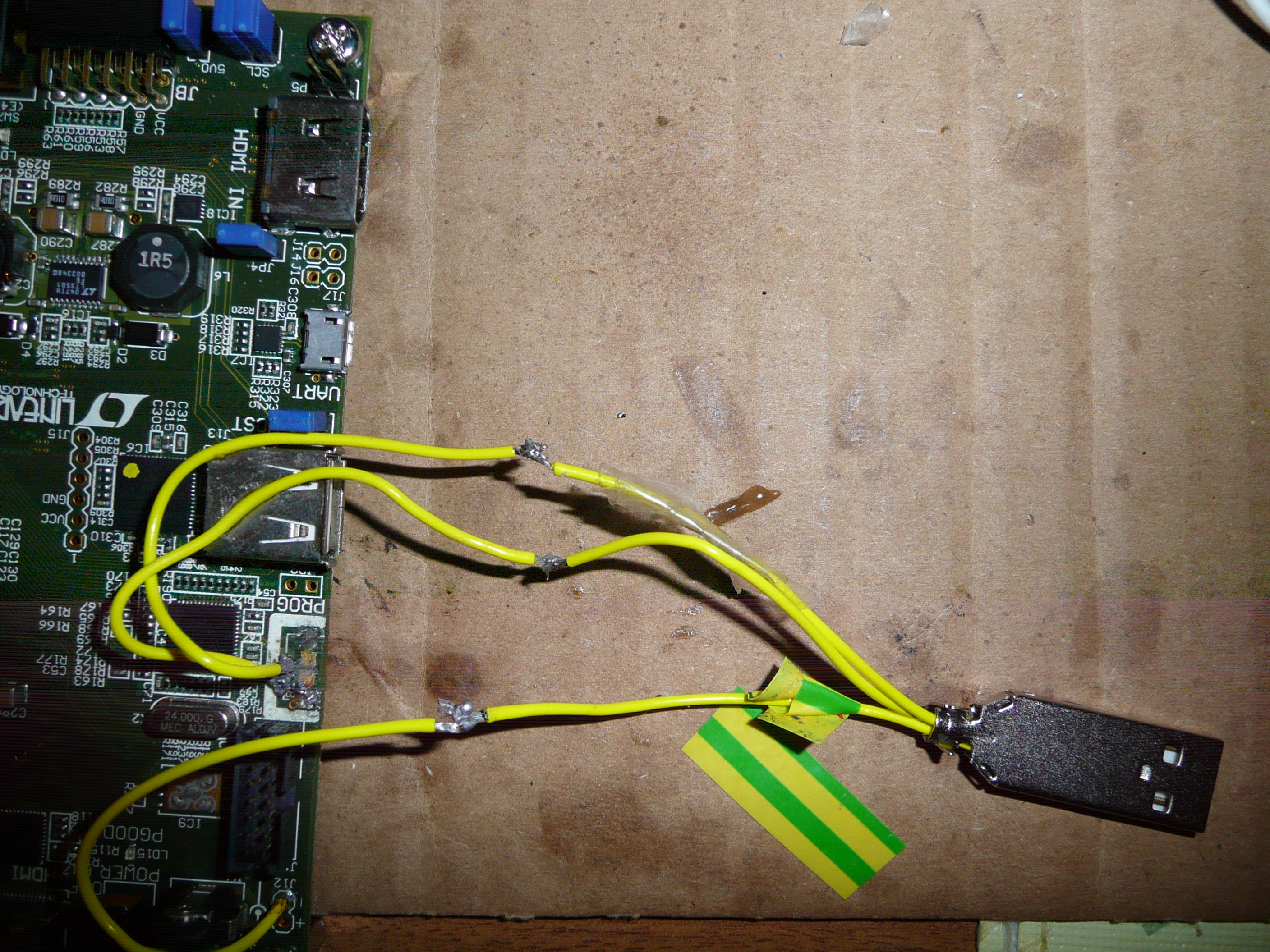
Does anyone know how should I repair myself this port, and if it is doable? My idea was that of soldering some wires to the pads.. and then trying to reconnect the signals to a USB port (even a different larger USB port...), and what about signal integrity.. if I mess up with USB signals (adding wires or pads or whathever...) isn't the risk of compromising signals integrity with parassite capacitances and stuff like that... and having problems with high frequencies USB signals?

Thank you very much


Here is the picture of the damaged Atlys board:
broken_atlys_details.jpg
 

From the previous thread:

Now I feel hopeless.... Is there some special LED that says the FPGA is being programmed or something? What type of filesystem did you use?

LEDS during usb stick programming (JP11 loaded): LD5 dimly lity, LD7 fully on. So when it's programming from the usb stick you should see 2 leds. One fully on, one dimly lit. As said, that lasts 29 seconds with the stick I used.

And purely FYI, when you program with usb (JP11 removed): Only LD5 is dimly lit. LD7 is off.

As for filesystem on the stick ...


Disk /dev/sde: 261 MB, 261750272 bytes
50 heads, 12 sectors/track, 852 cylinders
Units = cylinders of 600 * 512 = 307200 bytes
Sector size (logical/physical): 512 bytes / 512 bytes
I/O size (minimum/optimal): 512 bytes / 512 bytes
Disk identifier: 0x7afbf875

Device Boot Start End Blocks Id System
/dev/sde1 1 852 255594 c W95 FAT32 (LBA)

And I formatted it using "mkdosfs" under linux, basically because I'm too lazy to reboot without good reason. Doing the format under windoze should make no difference (i.e work equally well).

The main thing is just format it, and put it in the root with a short name.

As for repairing ... YOU! slowly .. step away from the soldering iron. Given your previous description I would suggest that maybe you want to practice it first on a scrap pcb. Old mobile phones make great smd soldering practice (and pll spare parts ;) ). Other than that for now I'd just clean up the pads to make sure there are no shorts. And then use either usb stick method or the jtag header.

I'd think that putting some more time into figuring out how to operate the usb stick is better spent than trying to resolder the usb connector.

I'll test in a minute what happens if I replace the valid bit file with an equaly large file with some random garbage.

---------- Post added at 19:01 ---------- Previous post was at 18:56 ----------

I just tested it with a 1484805 byte file (same as before) of all zero's (highly ordered random garbage :p ) and filename "test.bit".

Then it shows LD5 dimly lity, LD7 fully on after I turn on power. And it stays that way indefinitely.

---------- Post added at 19:06 ---------- Previous post was at 19:01 ----------

I hope you unpacked the .tgz file as stated in the other thread. If you didn't it will not work.

The file you should be putting on that stick should have this md5 checksum:

912b77143bb9111e53248b32d4f72f2e test.bit
 

Thank you for your patience and support,
I tried again this morning with a 4th memory stick.... always the same thing:
JP11 loaded, LD5 dimly lity, LD7 fully on.... after 30 seconds... nothing happened..... :-(
I tried again and again formatted 10 times all the sticks I had, tried Fat32, Fat and NTFS.... no one seem to work....
At this point I don't know what to do.... I contacted Digilent and they told me to try reformatting usb mems with FAT... I did but it didn't work... they should contact me again in few days... hoping they will be able to give me some solution... but for now...
I feel hopeless... at this point I fear like the only solution is buying the JTAG cable (which means waiting another month because you can only buy that on the internet and spending like 50$ more..) or trying to repair USB port myself.....
there is also the possibility that the board got damaged during my attempt at soldering... this would be horrific! but looking here:
Stromeko: FPGA Development Board 2 ? Digilent ATLYS Spartan6
..I see that I'm not the only one having problem with configuring the FPGA via USB HID, so there is still hope :)
In few hours (now I'm very tired...) I will check the board for shorts like you suggested although these shorts are unlikely INMHO....
 

When you plug the usb stick into the PC, what file size does it report for that .bit file that you have on the usb stick?
 

When you plug the usb stick into the PC, what file size does it report for that .bit file that you have on the usb stick?

test.bit has these properties:

Size: 1,41 MB (1.484.805 bytes)
Size on disk: 1,43 MB (1.507.328 bytes)
 

That seems right.

One other thing that I can think of. If it is one of those "U3 smart" sticks, then the usb enumeration process may go different. This could affect simple loaders like thing. Again not sure since I have not tested this.

But that is something digilent support should be able to tell you. After all, the load .bit file from usb stick is is a feature they advertise as working.

I've used a boring old low capacity stick and that worked without having to do anything special.
 
Hello,
no they are not U3 smart...
BTW, I just checked for shorts on the USB Adept port.. there are none...

I have thought abount a thing: what about jumpers? Maybe I have a jumpers configuration different from yours... and that may (in some ways) affecting my board..
many of these jumpers are not even documented on the Atlys manual...
 

None of the other jumpers has anything to do with this. So there is as much value to me giving the list of my settings, as there is to you just randomly trying every combination. I don't see how it is going to make a difference.

The other jumpers closest to JP11 have to do with HDMI, with i2c and with VCC on the 12 pin IO connector.
I don't know. Take a good look at the partition table I listed earlier and make sure you have the exact same partition type. Do a full format. Make sure only the 1 .bit file is on it. If you have a large stick, make your own partition table with just a single partition of 256 Mb on it, etc.

Another thing you could try is use a usb harddisk. It's all mass storage after all... Again, you can play with fdisk to change partitions if you need to.

Be creative. :p I think the stick still is your current best bet. Other than that it would be interesting to know what digilent has to say on any limitations with the usb stick approach.
 

I tried formatting my Kingston 4gb usb mem with mkdosfs...created a FAT32 partition... it didn't work :-( I haven't tried yet to recreate the same partition with the data you told me.. I have no idea how to do it with mkdosfs... do you know the command line to recreate that exact same partition?
Anyway.. I tried to repair the Adept USB port, I have connected 3 wires to the pads (GND, D- D+) and connected them to a USB male plug...
the homemade connections are shown in the picture...

here the final result:

I tried to plug it into my computer... it didn't work... the PC does not even recognize the device.... I installed Adept software (with drivers)... but no success... I have doublechecked the signals and continuity test was OK... but still..nothing
what can be the problem?Maybe signal integrity was broken?

Today I ordered a JTAG cable from China.. it costed me 40$ (shipping is free).. I will probably receive it in a month or something.. probably that will be my last hope to configure the Atlys...
 

@_@

You couldn't find any thicker wire? Based on those pictures there's quite a few things that could have gone wrong. I would suggest buying flux, getting solder wick, getting thinner wire, and practice on something else than that poor atlys board.

As said, your best hope is the usb stick. Especially before your impatience kills the board further. :p Did you get any reply from digilent on the usb stick stuff?

Commands for partition things and such. All that you need under linux for this are "mkdosfs" and "fdisk". Also, "man fdisk".
 
Last edited:

I tried to plug it into my computer... it didn't work... the PC does not even recognize the device.... what can be the problem?

Have you thought about taking a hammer to it and putting it out of its misery?

I believe it's time to take a step back, take a few deep breaths and hand the soldering iron over to a friend or colleague who knows how to solder/desolder. And then have them attempt to clean up the mess you have made.

As mrflibble suggested, for the time being, wait for the USB stick or the JTAG programming cable. Out of curiosity, why didn't you order a JTAG cable from Digilent? For another $15 to $20 they could have delivered a JTAG cable to you within a week or two, maybe sooner.

Don't despair, things often appear worse then they are. Just don't try and repair/solder anything else. If the traces are gone and there are no vias available to tap into, an extremely skilled individual should be able to rig a USB connector directly to the Cypress device. You just need to find someone with the require skill level and of course compensate them for their time.

BigDog
 

I have Windows 7, tried with mkdosfs (for Windows) but was not able to create that same partition as mrfibble suggested (apart from selecting logical sector size as 512).. (there are no commands with mkdosfs to do custom partitioning like that...).. I'm looking for partitioning programs for Windows7 to create a partition identical to that of mrflibble...

This morning I tried using my custom USB plug again, checked signals (D-,D+, GND.. they all seem good), inserted it into my PC.. but nothing happened..

Just a question: what happen after the FPGA has been programmed with test.bit? Do the leds start suddenly litting on (according to switches configuration).. even if mem stick is STILL in and jumper jp11 is still on, or should I reboot the board to see the leds?
 

I'm looking for partitioning programs for Windows7 to create a partition identical to that of mrflibble...

This calls for ... google "create partition windows 7".

This morning I tried using my custom USB plug again, checked signals (D-,D+, GND.. they all seem good), inserted it into my PC.. but nothing happened..

I applaud your perseverance. :p But you would do well to forget that horrendous blob of solder induced fpga board torture.


Just a question: what happen after the FPGA has been programmed with test.bit? Do the leds start suddenly litting on (according to switches configuration).. even if mem stick is STILL in and jumper jp11 is still on,

Yes.

or should I reboot the board to see the leds?

No.

After programming is succesful, you will clearly see the difference in led state.

So what did digilent have to say on the matter of programming from usb stick?
 

Try this format utility for windows, maybe it helps

Alex
 

Attachments

  • USB_format.zip
    369.3 KB · Views: 67

For experts only: What type of special cares should we take when dealing with USB?

Hello,
I'm writing this post because I'd like to know what type of signals are those used in the popular USB connections. For what I 've understood,
the signal in USB cable is a differential signal, there is a differential pair (D+, D-), this means that there is a special care that we must take when implementing connections, cables, ports dealing with these signals. My question is: what are these special cares?

I ask this because, some days ago, I was working on a board and a micro USB port broke, I tried to repair it by soldering some wires to the microUSB pads.. but the device didn't work... I fear that I didn't take proper measures to deal with differential signals...
The picture of my attempt to repair the USB port is here:

https://obrazki.elektroda.pl/51_1318448488.jpg

Can anyone confirm me that the reason why this solution does not work, is because differential pair signal integrity was very probably broken?


Please keep posting in the same thread, don't create new ones. Threads merged [alexan_e]
 

Re: For experts only: What type of special cares should we take when dealing with USB

Can anyone confirm me that the reason why this solution does not work, is because differential pair signal integrity was very probably broken?
No, it seems that you've been "cutting the toothpich with the axe" :lol:

Find a friend/colegue who knows how to hold the soldering iron "from the right side" and change the wires that you've used those are waaaaay too thick.
 
  • Like
Reactions: FvM

    FvM

    Points: 2
    Helpful Answer Positive Rating
This calls for ... google "create partition windows 7".


I applaud your perseverance. :p But you would do well to forget that horrendous blob of solder induced fpga board torture.


Yes.


No.

After programming is succesful, you will clearly see the difference in led state.

So what did digilent have to say on the matter of programming from usb stick?
Digilent told me that I should format the mem stick to FAT (I did but it didn't work either). They also told me that the .bit file must be compatible with the FPGA, otherwise the board rejects it... well I think the .bit file is compatible,
..anyway at this moment I'm totally hopeless.... I'm not even sure the JTAG programmer I will receive in about 20 days (hopely) will work....
Even if the JTAG or stick will at last work.. well I will anyway find myself with a board which is not the board I paid for... I have thought about this, I need a fast port to store on a external device the frame grabbed from HDMI input port to realize my portable HDMI recorder... the USB Adept port would have been perfect for that... but now that it is gone?

---------- Post added at 23:16 ---------- Previous post was at 23:15 ----------

Try this format utility for windows, maybe it helps

Alex

Thank you, I tried with this utility... but it didn't work either... :-(
 

If I understand correctly mrflibble has the same board and he managed to make it work, maybe he can upload his bit file which works for sure so that you can try it too and at least you will be sure that the bit part is correct and search for another cause if it still doesn't work.

Alex
 

Re: For experts only: What type of special cares should we take when dealing with USB

No, it seems that you've been "cutting the toothpich with the axe" :lol:

Find a friend/colegue who knows how to hold the soldering iron "from the right side" and change the wires that you've used those are waaaaay too thick.

Exactly this. :p

No man overboard, it can probably still be fixed, but STEP AWAY FROM THE SOLDERING IRON! Please let someone else do it.
 

..anyway at this moment I'm totally hopeless.... I'm not even sure the JTAG programmer I will receive in about 20 days (hopely) will work....

Unless the Spartan 6 is damaged, a Xilinx compatible JTAG programmer will work. If the Spartan 6 is not JTAG'able then no USB connector can help you.

As far as the damaged USB connector, it can be repaired. I would strongly suggest you find someone in your area who is skill in SMD rework/soldering. Take the board and a copy of the schematic to them for an option/estimate. Looking at the photos, I see no reason a person skilled in SMD rework could not repair/rig a USB connector for you.

Obviously, rework/soldering is not your forte, so let a professional repair it for you.

BigDog
 

Status
Not open for further replies.

Part and Inventory Search

Welcome to EDABoard.com

Sponsor

Back
Top