Continue to Site

Welcome to EDAboard.com

Welcome to our site! EDAboard.com is an international Electronics Discussion Forum focused on EDA software, circuits, schematics, books, theory, papers, asic, pld, 8051, DSP, Network, RF, Analog Design, PCB, Service Manuals... and a whole lot more! To participate you need to register. Registration is free. Click here to register now.

[Moved]: DC-DC controller recomendation/finder

Status
Not open for further replies.

skenn_ie

Newbie level 4
Joined
Jan 1, 2010
Messages
5
Helped
0
Reputation
0
Reaction score
0
Trophy points
1,281
Activity points
1,327
Hi All. I have been looking for a controller for an isolated DC-DC converter with at least 3 interleaved phases. Ideally, the controller should have an SPI or IIC interface to adjust the dutycycle/Vout and read back Vout to an Arduino., but I could fool the regulator by using an SPI or IIC pot in the feedback circuit. I want to use a 16 - 20V power source, and similar on the isolated output. That would work well if Vout on the primary was maybe 10V. A high transformer ration isn't good in my experience.

Can anyone recommend a controller for this ?

Thanks
 

say you set D high for max load, then suddenly someone suddenly disconnects the load.....how do you ensure your output voltage doesn't sky high......I suppose you need output overvoltage trip, but better still , you need a negative feedback loop to control the D...if you do that in software then that is very difficult...a co called converter technology in reading are tryin gto make a range of controllers that close the loop in software, and all us the user does is literally key in what we want vout to be, fsw, feedback loop bandwidth etc.
 

The load, a battery, will be permanently connected. The output will be isolated.
I may have to program a PIC, but had hoped to find a single chip to do the 3-phase interleaved PWM, the only ones I have found are for high current, sub 3V work.
 

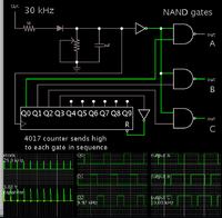
Here's a possibility for experimentation...

4017 counter IC rotates pulses to 3 Nand gates. This yields control signals which are staggered 120 deg. Duty cycles overlap.

You can adjust duty cycle within certain limits, by the diode-resistor-capacitor network.


By substituting 'And' gates, you get a different pattern of 'On' times, and a different range of duty cycles.

You are not limited to just 3 outputs with a 4017 IC.
 

look at UCD-series (UCD3138, etc) from TI
 

Status
Not open for further replies.

Similar threads

Part and Inventory Search

Welcome to EDABoard.com

Sponsor

Back
Top