Neetha Patil
Junior Member level 2
Hello sir
I am doing thesis on Arichetecture of Dynamic Current Mode Logic , so i have to create MCML symbol for it . How to simulate a MCML Symbol and how can be it conneected. i am attaching some pics
this is the DYCML arichetecture


the above schmatic is MCML Inverter and from this i created Symbol as shown below

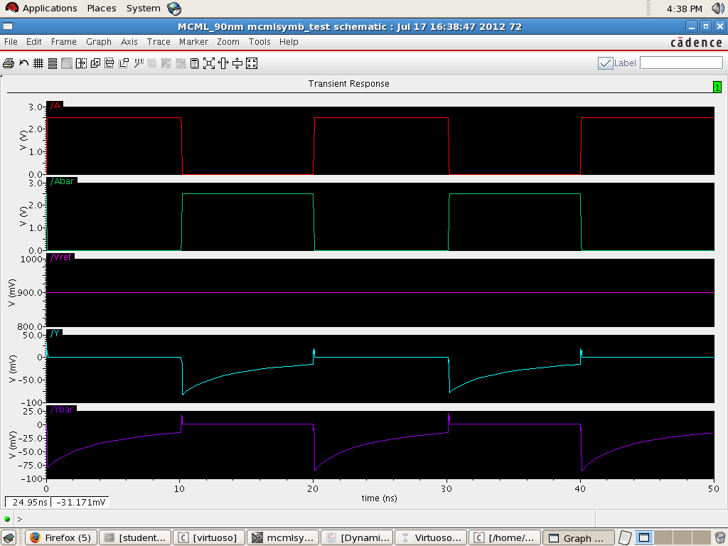
In symbol can we connect pins as in schematic ? or else have to take VPulse as inputs? i am not getting exact result for the symbol ,getting spikes in output .

why like that ,please help me sir
Thank You in Advance
I am doing thesis on Arichetecture of Dynamic Current Mode Logic , so i have to create MCML symbol for it . How to simulate a MCML Symbol and how can be it conneected. i am attaching some pics
this is the DYCML arichetecture

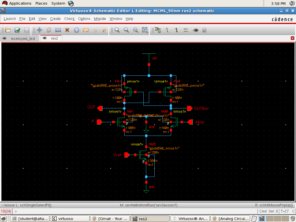
the above schmatic is MCML Inverter and from this i created Symbol as shown below
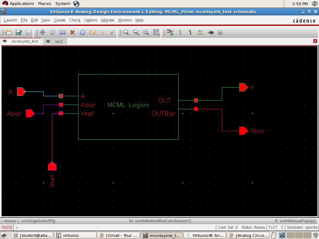
In symbol can we connect pins as in schematic ? or else have to take VPulse as inputs? i am not getting exact result for the symbol ,getting spikes in output .
why like that ,please help me sir
Thank You in Advance
Last edited:
