Continue to Site

Welcome to EDAboard.com

Welcome to our site! EDAboard.com is an international Electronics Discussion Forum focused on EDA software, circuits, schematics, books, theory, papers, asic, pld, 8051, DSP, Network, RF, Analog Design, PCB, Service Manuals... and a whole lot more! To participate you need to register. Registration is free. Click here to register now.

Measurement of Phase difference with 4046

Status
Not open for further replies.

Bilal_Ahm

Junior Member level 2
Joined
Apr 10, 2014
Messages
24
Helped
1
Reputation
2
Reaction score
1
Trophy points
3
Activity points
188
Hi,

My problem is to calculate the phase difference. sine wave was with frequency 10KHz and amplitude is 100mV. Resistor and capacitor are in series. Due to the capacitor there is a phase difference and that can also be seen in the simulation that i uploaded. How i can use 4046 IC or any other thing to calculate phase difference in terms of voltages that can read by the ADC of microcontroller.
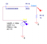
circuit.PNG

Simulation.PNG


red one is the output that is not in phase to the input which is blue one.


Thanks in advance.
 

The most accurate way is to use an accurate clock that runs much faster and count the time interval. If counting is not possible, a DAC could be connected to counter to read as Analog.


The Type I is just an XOR Gate mixer so with steady frequency and Vcc, the average phase voltage can be measured for 90 deg +/-90deg shift which can be a problem with the limiter and ripple with jitter.

The Type II is a Phase frequency mixer is good for +/-180 deg
Similar problems with ripple and jitter.
 
The way I did it, is similar Sunnyskyguy mentions:
A 74HC4060 counter toggled with a much higher frequency. It was started with the zero crossing of the reference signal, and stopped with the zero crossing of the delayed signal.

The4060 outputs fed a binary weighted resistor network to form a rudimentary DAC, and fed to an opamp.
 
Using an XOR gate will give an average (filtered) output voltage that is a function of the phase difference between the two inputs.
You need to square up the sinewave signals using two comparators that detect the signals' zero-crossings.
Feed the two outputs into a CMOS XOR gate with an RC filter on its output.
The filtered output will vary from 0V for zero phase shift to the XOR's supply voltage for near180° phase shift.
This circuit does not determine whether the phase is leading or lagging.
 
The most accurate way is to use an accurate clock that runs much faster and count the time interval. If counting is not possible, a DAC could be connected to counter to read as Analog.


The Type I is just an XOR Gate mixer so with steady frequency and Vcc, the average phase voltage can be measured for 90 deg +/-90deg shift which can be a problem with the limiter and ripple with jitter.

The Type II is a Phase frequency mixer is good for +/-180 deg
Similar problems with ripple and jitter.

hey thanks sunnyskyguy for helping me. as i am new to these topics, i did not get it fully. XOR gate mixer with steady frequency. but the output will be the Rail to rail of XOR gate. isn't is? in the case when i only use XOR gate as a mixer?

and i want to measure the phase difference from 0 to any, a analoge dc should represent the signal as a voltage value.

- - - Updated - - -

The way I did it, is similar Sunnyskyguy mentions:
A 74HC4060 counter toggled with a much higher frequency. It was started with the zero crossing of the reference signal, and stopped with the zero crossing of the delayed signal.

The4060 outputs fed a binary weighted resistor network to form a rudimentary DAC, and fed to an opamp.

Hi schmitt trigger, thanks man for helping, i found your solution interesting. from the datasheet of 74HC4060 i saw, Q3 to Q9 is one output port, and Q11 to Q13 is another output port of binary counter. at pin 9 and pin 10 there must be resistor and capacitor connected for oscillations and Rt and Ct i can select. the thing i do not understand is what goes to RS pin 11 and MR pin 12. and how we can collect the analogue signal from output ports. you said by outputs fed a binary weighted resistor network to form a DAC, and fed to an op amp. how i am going to interface with the op amp? do you mean i should connect each output pin to the op amps or there must be some resistor attached to the output ports and making a single node then that node should fed to op amp? by this solution can we detect phase dif. of a 100mv signal with frequency range 1 kHz to 10KHz? it would be very helping if you can give some schematic from your previous work that you have done.

Regards
Bilal Ahmad

- - - Updated - - -

Using an XOR gate will give an average (filtered) output voltage that is a function of the phase difference between the two inputs.
You need to square up the sinewave signals using two comparators that detect the signals' zero-crossings.
Feed the two outputs into a CMOS XOR gate with an RC filter on its output.
The filtered output will vary from 0V for zero phase shift to the XOR's supply voltage for near180° phase shift.
This circuit does not determine whether the phase is leading or lagging.

hi crutschow thanks man for the interest to help me.

1) i do the square wave conversion by comparators, then outputs of comparators should fed to XOR with an RC filter. which filter you are talking about, the one that i have or some other filter i have to add at the output of the XOR gate? and by this solution we can get voltage range varying with respect to the phase dif. from rail to rail of the XOR gate.

am i right?
i do not need leading or lagging phase i only have capacitor so phase must be negative.

any specific parts you recommend or i can use simple camparator and op amps.

Regards
Bilal ahmad
 

i did not get it fully. XOR gate mixer with steady frequency. but the output will be the Rail to rail of XOR gate. isn't is? in the case when i only use XOR gate as a mixer?

and i want to measure the phase difference from 0 to any, a analoge dc should represent the signal as a voltage value.

Regards
Bilal ahmad

The '4046 PLL has 3 phase detectors classified as type I,II,III
Type I is just an XOR gate with a LPF out. Good for averaging jitter to centre a PLL clock 90deg offset from data edges but poor for measuring phase error.

Reasons are; excess time delay with long time constant 100x. excess ripple at 10x and 1x
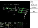
XOR mixer.jpg

You can adjust delay here and see the result in min/max ripple and average and time delay. of XOR problems. It works for crude measurements but many sources of error.
https://goo.gl/rQy6Gu


The counter method is much more accurate with a bit of averaging.
 
??? that link is about ADC/DAC principles not phase measurement.

Brian.

Brian;
I know.
This is because Sunnyskyguy and myself have recommended using a counter method, and I'm showing how to generate an analog output (OP's original requirement) from a counter using a resistor ladder.
 
OK, understood. It goes into far more detail than necessary though and possibly confuses matters with all the other technologies.

Brian.
 

Yes, there are many ways to skin a cat.

The example I indicated is because many moons ago, without the benefit of a microcontroller, I had to design a quite accurate power factor meter for power line applications.

The OP may not require that much precision, or may require something simpler, but I'm pointing out the way I did skin the cat in the past.
 
thank you sunnyskyguy you really helped me. now i understand whats really going on.

- - - Updated - - -

Bilal;
check the following explanation. It is a little lengthy but worth reading all:

https://www.ibiblio.org/kuphaldt/electricCircuits/Digital/DIGI_13.html

Thanks schmitt trigger it really helped. now i have idea how to get Analogue voltages from 4060 counter. i have bought the 4060 chip and mcp6002 op amp. i want to measure phase diff at the output which is first capacitor and resistor in series that should goes to RS (pin 11) of the 4060 chip and where i have to connect my reference which is supply in my case 1kHz 100mV? is it CLR (pin 12) or MR just needs to be digitally high or low for the operation? and at pins 9 and 10 a oscillator should be connected with high frequency may be 20MHz? if i understand not wrong then at both counter outputs i can get 3 bit resolution as well as 7 bit resolution at the same time. but i can not get 10 bit resolution as combined?

any suggestions?

i have understood the binary weighted DAC it was really helping. now i know how DAC works. :)
 
Last edited:

You have to
1- clear the counter
2- detect the zero crossings of your reference which will start the counter
3-let it run clocked from an accurate reference
4-stop it at the zero crossing of the delayed waveform
5-read the adc value.
6-repeat.

Some external gating to the 4060 may be necessary.
 
You have to
1- clear the counter
2- detect the zero crossings of your reference which will start the counter
3-let it run clocked from an accurate reference
4-stop it at the zero crossing of the delayed waveform
5-read the adc value.
6-repeat.

Some external gating to the 4060 may be necessary.

by using zero crossing detector for reference as well as the delayed output. thanks alot. :)
 

A phase measurement assumes both signals are the same frequency.

Then a phase error is simply the time interval from one signal to the next. One can choose a third clock that is much higher so thatmit does not need to be synchronous , e.g. 1000x or a synchronous clock only 360x .

In either case, the phase is simply a count using the both edges to determine the window of counting. Start/stop is just a FF using set/reset or similar to enable the counter.

A 4046 offers no advantage unless you use it as a PLL to create a synchronous clock N x the input freq using a divider in the loop outside the 4046 VCO.

When I wanted to measure phase modulation for a 400MHz transmitter, I used a precision, HP Time Interval Counter to measure phase shift.

It would be better if you define your reference clock, input signal and desired phase resolution.
 
Status
Not open for further replies.

Similar threads

Part and Inventory Search

Welcome to EDABoard.com

Sponsor

Back
Top