Continue to Site

Welcome to EDAboard.com

Welcome to our site! EDAboard.com is an international Electronics Discussion Forum focused on EDA software, circuits, schematics, books, theory, papers, asic, pld, 8051, DSP, Network, RF, Analog Design, PCB, Service Manuals... and a whole lot more! To participate you need to register. Registration is free. Click here to register now.

Solving difference amplifier with capacitor with equations

Bjtpower

Full Member level 5
Joined
Dec 24, 2015
Messages
297
Helped
2
Reputation
4
Reaction score
2
Trophy points
1,298
Activity points
3,893
Hi,
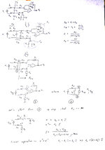
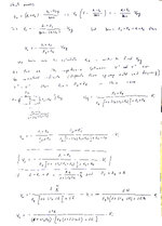
I would like to learn Difference amplifier and its equation when capacitors are connected in Feedback like below
My intension understand capacitor impact and its equation for learning purpose.
1697740881323.png
 
Do you know how to do analysis of the circuit WITHOUT the capacitors? If so, then the capacitors are just impedances: 1/sC (or, 1/jwC). Sorry, reactances are messier than plain resistors.

If you don't know how to analyze an opamp circuit, then I can just tell you the capacitors act add some low-pass filtering. In your circuit they're pretty small, so they're probably just there for noise reduction.
 
The differential inputs are unbalanced for impedance and gain.
The inverting input gain is -44 dB with a breakpoint at 0.5MHz due to C7 and around 15 MHz from C8.
The VAC- input (neutral) has less attenuation -17 dB. and a similar breakpoint at 0.5MHz.

You can plot each input separately.


What specs would you like for attenuation, impulse rejection and noise filtering?
 
All those caps. 4.7 pF, seem to be stray C representations, eg. layout
generated C and package C......? Except for C7

"Normally" one uses LaPlace s plane analysis on this, but the # components
would make the algebra challenging.

Consider using signal flow graph analysis to get to T(s) (transfer Function).


Regards, Dana.
 

Attachments

  • Signal Flow Graph 2.zip
    32.8 KB · Views: 31
Do you know how to do analysis of the circuit WITHOUT the capacitors? If so, then the capacitors are just impedances: 1/sC (or, 1/jwC). Sorry, reactances are messier than plain resistors.

If you don't know how to analyze an opamp circuit, then I can just tell you the capacitors act add some low-pass filtering. In your circuit they're pretty small, so they're probably just there for noise reduction.
Hi,

I would be happy if you help with me some equations, how they play roles? No matter if they are smaller or higher values.
 
Basic OpAmp differential analysis :


One way of doing this is create a diagram where you replace
a series RC or parallel RC with a symbol, say Z1, Z2, .... Then you
write node and loop equations and solve. Then sub back into
your analysis the values for Z1.

A parallel Rc Z1 = (R x 1/sC) / ( R = 1/sC)

Good luck, can be very tedious if a large number of passives involved.

Reason for using signal flow graph analysis with a utility.


Are you a student with an assignment ?


Regards, Dana.
 
Here is my analysis. It should be valid as far as the op-amp can be considered (almost) ideal. If the frequency increases and the input capacitance (between inverting and non-inverting pin) starts to play a role this quite simple math loose validity. How much can be high the frequency depends from the used op-amp.
 

Attachments

  • DiffAmp1.jpg
    DiffAmp1.jpg
    557.3 KB · Views: 36
  • DiffAmp2.jpg
    DiffAmp2.jpg
    562.2 KB · Views: 38

LaTeX Commands Quick-Menu:

Part and Inventory Search

Welcome to EDABoard.com

Sponsor

Back
Top