Hi Leo,... it is worth raising doubt for that the circuit will achieve 20% current accuracy.
raising doubt with good cause always is legitimate ;-)
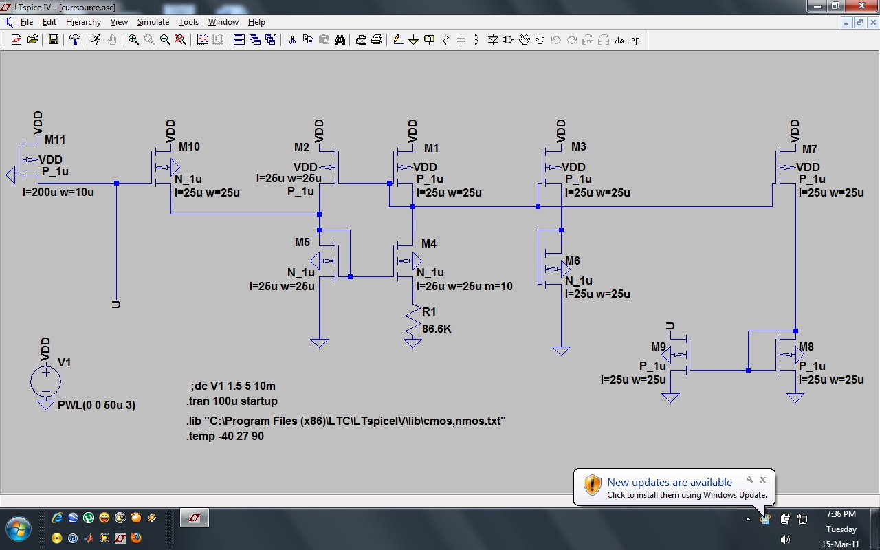
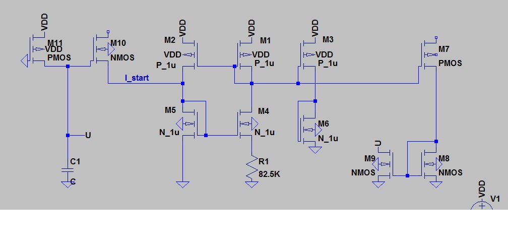
k5 simply is the W/L ratio of mosfet M5. Its effect is described in equ. (9), and considered in the following equations through the defined ratios p, t, & l (p. 3805 of the paper).It is related to k5 that is process dependent. k5 effect is not described in the paper.
The essential idea behind this current stabilization process relies on the (admittedly) process-dependent n/p mobility ratio, which can be compensated by appropriate choice of the k- resp. W/L ratios. Of course the resulting design is not transferable to other processes, probably not even to other processes with the same structure size.
For additional info, you might want to communicate with the authors of the paper directly.
")