Continue to Site
Follow along with the video below to see how to install our site as a web app on your home screen.
Note: This feature may not be available in some browsers.
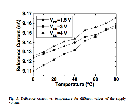
I need to design a l-p l-v current source , Vin=3->5,5 V ; Iout=1µA +/- 20% ; T=-40 degree(C)...90 degree(C)
... any further information is welcome
It is hard to have +/-20% current accuracy in standard process.
... Usually resistor will take >+/-30% variation.
... Is the originally requested 20% initial accuracy feasible without trimming?
Hi Leo,
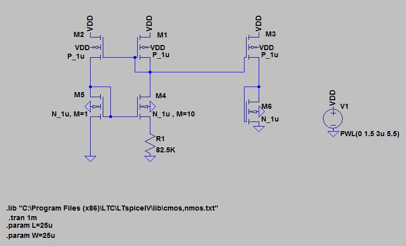
didn't you read this paper from above? A CC source can be designed without resistor, only for an individual, process-dependent (µn/µp ratio dependent) current, however. But this current can be multiplied arbitrarily, of course.
