Continue to Site

Welcome to EDAboard.com

Welcome to our site! EDAboard.com is an international Electronics Discussion Forum focused on EDA software, circuits, schematics, books, theory, papers, asic, pld, 8051, DSP, Network, RF, Analog Design, PCB, Service Manuals... and a whole lot more! To participate you need to register. Registration is free. Click here to register now.

light emitting diode control differ controls

Status
Not open for further replies.
Hi,

MCU pin voltage is 5V, Vbe = 0.7V, Ib = 60 mA

These are somehow "ideal" values.

Read your microcontroller´s datasheet.

Maybe you find int the "Absolute maximum Ratings" something like this:
"DC Current per I/O Pin ............................................... 40.0 mA"
Then you can´t draw 60mA from any pin.

And if it can source 60mA, then you should look into "IO pin voltage current chart"
Maybe it looks like this:
IOChart.png
Then find the 60mA horizontal line and find out that the output voltage may be 3.2V only. (not 5V)

*****
--> I recommend to use a MOSFET instead of the bjt.

Klaus
 

That transistor's collector is consider for our load current.?
Collector current is consider for load.?
 

Use MOSFET as advised. It is a voltage controlled device and hence you need not worry about the gate current. If you are using PIC then its output pin can source or sink only 25 mA.

Mosfets are better. Use Logic gate N Channel Mosfet.

FDN361BN Rds(on) = 160 mOhms
RSF014N03 Rds(on) = 240 mOhms
SCH1436 Rds(on) = 160 mOhms

You can directly connect the gates of these mosfets to PIC, AVR, 8051 output pins. Lamp will be between 12V supply and Drain. Source will be grounded. A 10k resistor between gate and source.
 
Last edited:

datasheet.pngupload.png


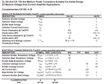
i attached CK100 transistor datasheet..In that they mentioned collector current is 1A..whether it is suitable for my project...

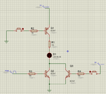
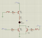
In this circuit I used BC557 to control the positive side of LED...On negative side i use two BC547 to control the negative supply.... When the BC557 is switched and BC547 is switched without pwm,the LED will glow normally....

BC547 is switched by PWM means LED will glow based on PWM pulse...

Is this circuit is correct..?It will work fine..?Or any changes I have to make..?

- - - Updated - - -

we need to use both transistor at high collector current rating..?
Or on positive only enough..In negative side can we use normal transistor like BC547..
 

Hi,

Believe in the calculations above, or make the calculations on your own.

Calaculate necessary base current for the CK100. Is your microcontroller able to drive this current?
What´s wrong with the recommended mosfets?

we need to use both transistor at high collector current rating..?
For each transistor you know how much (max) segments are ON at at time. And you know the necessary segment current. Multiply both values and get the necessary transistor collector current.

Hint:
A full schematic may help you to find the solution on your own. With just one single LED the total current is not obvious.

Klaus

Added:
Isn´t your schematic from a simulation tool? Then you simply could show the necessary currents and their waveforms.
 

i need to control one LIGHT only
Thats all my circuit....

Instead of LED in my live project i will use 12V/6W induction bulb...
Then remaining everything is same as like circuit...

- - - Updated - - -

I need to operate the lamp in both main supply and based on pwm pulse like dim and bright

- - - Updated - - -

I need to dim and bright lamp and need to control the lamp from power supply in single pin so designed this circuit....

In main supply it will work fine but my doubt is whether pwm work under this condition or i have to modify the circuit..?
 

Two transistors can be used like BC337 and SL100. The emitter of BC337 will be connected to base of SL100. contolling base current of BC337 will control its emitter current and emitter current of BC337 will be base current for SL100. There will be two Vbe in series so, you have to choose base resistor for BC337 such that 5 - 1.4V drop across the resistor.
 

in positive and negative side we need same collector current transistor for pwm control and normal switching control..?
Or we can reduce collector current on negative side..?
 

One single mosfet is enough to drive the Lamp. No need for positive and negative side switch. All you need is a simple Mosfet Switch.
 

Hi,

Ok, sorry I mixed it with onother thread...

****
Anyway, the informations in this thread are confusing for me.
In your schematics I only see 5V, but in your descriptions you talk about 12V bulb. What is true now?
Is it an incadescent bulb? (What is induction bulb?)

Another thing confuses me:
Sometimes you have two control lines, now you have three control lines. Why?

To
* switch OFF
* switch ON
* to dim
a bulb, you just need ONE control line.

(driving an n-CH low side mosfet)
* bulb is OFF, when signal is low
* bulb is fully ON when signal line is HIGH
* bulb is dim when signal line is PWM´d

If you use two signal lines you can connect them in AND configuration or in OR configuration.
In AND configuration both signals need to be ON for the bulb to glow.
In OR configuration the bulb glows if one or both signals are ON.
What function do you need?

Describe where does each signal come from.


Klaus
 

in AND configuration
Positive supply is constant...Their is no PWM on that...
If i switched on Positive transistor means supply is given to bulb...

I used to control the bulb whether it working under normal condition or under PWM condition on negative side....
Switch ON OFF determined by positive side...
Whether the bulb working on normal condition or PWM condition determined by negative side
 

Hi,

please answer ALL questions.

Klaus
 

You just refer my circuit in that i used three transistors...
One to control positive voltage to bulb....
On negative their are two transistor to control negative supply to control....
one to control direct negative supply another one is negative is controlled through PWM pulse...

Working principle...
when Positive side transistor is switched ON positive supply given to bulb....
On other hand the transistor which connected directly to ground is switched on,the led will glue without based on PWM pulse...

On another condition when PWM transistor is switched ON based on PWM pulse the bulb controlled through PWM.At this stage another transistor on negative side will turned OFF...


This is my operation.I designed the circuit as shown before...Is their any problem with that..?
 

Hi,

You just refer my circuit in that i used three transistors...
This is one of my questions...
--> I don´t know which schematic is true. Please tell us. Everything.

(Please understand that I don´t want to spend more time, as long as you don´t give complete and precise informations)


Klaus
 

upload.png

this schematic...When Q1 is switched on positive is given to LED....
If Q2 is switched ON LED will glow as normal operation..During this time Q3 will be in off state....
If i need PWM operation means Q3 is switched using PWM pulse..During this time Q2 at OFF state...


My questions are...
Is this circuit is correct..?
Need to use same transistor value on both positive and negative side..?

in real time hardware i will use induction bulb with rating of 12V/6W
 

What is induction bulbs ? Do you mean halogen bulbs ?
 

Sorry friends i'm making this conversation length....
i'm new to electronics and embedded software...

I making every projects from my basic knowledge....
Thats why lot of confusion and doubts on my side....
 

Hi,

Sorry friends i'm making this conversation length....
i'm new to electronics and embedded software...

Is it asking too much to answer some basic questions like supply voltage for the bulb?

Klaus
 

Status
Not open for further replies.

Similar threads

Part and Inventory Search

Welcome to EDABoard.com

Sponsor

Back
Top