Microwave123
Member level 2
Hello all,
First of all, I am using HFSS to simulate this structure.
Substrate: 99.5% Alumina
Trace: Copper
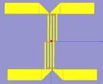
I need help and advise on how I can solve this problem. I designed a Lange coupler that looks like the one below. The response looks fine when I did not add the extra 50 ohms microstrip lines on the 4 ports. However, when I change the length of the microstrip line to a very long length, The response of the coupler looks completely different going from equal coupled to undercoupled. I am expecting the coupling to be the same.
Also, the coupled port and direct port only has a phase difference of about 85 degrees. From my simulation results, I figured that as the separation between the fingers gets smaller, the phase difference is a lot closer to 90 degrees. The problem with small separation is as the separation gets smaller, the response gets way overcoupled.
I don't understand why this is happening. Please comment and discuss. This is an urgent project.
Thank you!
First of all, I am using HFSS to simulate this structure.
Substrate: 99.5% Alumina
Trace: Copper
I need help and advise on how I can solve this problem. I designed a Lange coupler that looks like the one below. The response looks fine when I did not add the extra 50 ohms microstrip lines on the 4 ports. However, when I change the length of the microstrip line to a very long length, The response of the coupler looks completely different going from equal coupled to undercoupled. I am expecting the coupling to be the same.
Also, the coupled port and direct port only has a phase difference of about 85 degrees. From my simulation results, I figured that as the separation between the fingers gets smaller, the phase difference is a lot closer to 90 degrees. The problem with small separation is as the separation gets smaller, the response gets way overcoupled.
I don't understand why this is happening. Please comment and discuss. This is an urgent project.
Thank you!