Sajjadkhan
Full Member level 5
- Joined
- Sep 25, 2010
- Messages
- 307
- Helped
- 17
- Reputation
- 34
- Reaction score
- 16
- Trophy points
- 1,298
- Location
- Rawalpindi,Pakistan
- Activity points
- 4,199
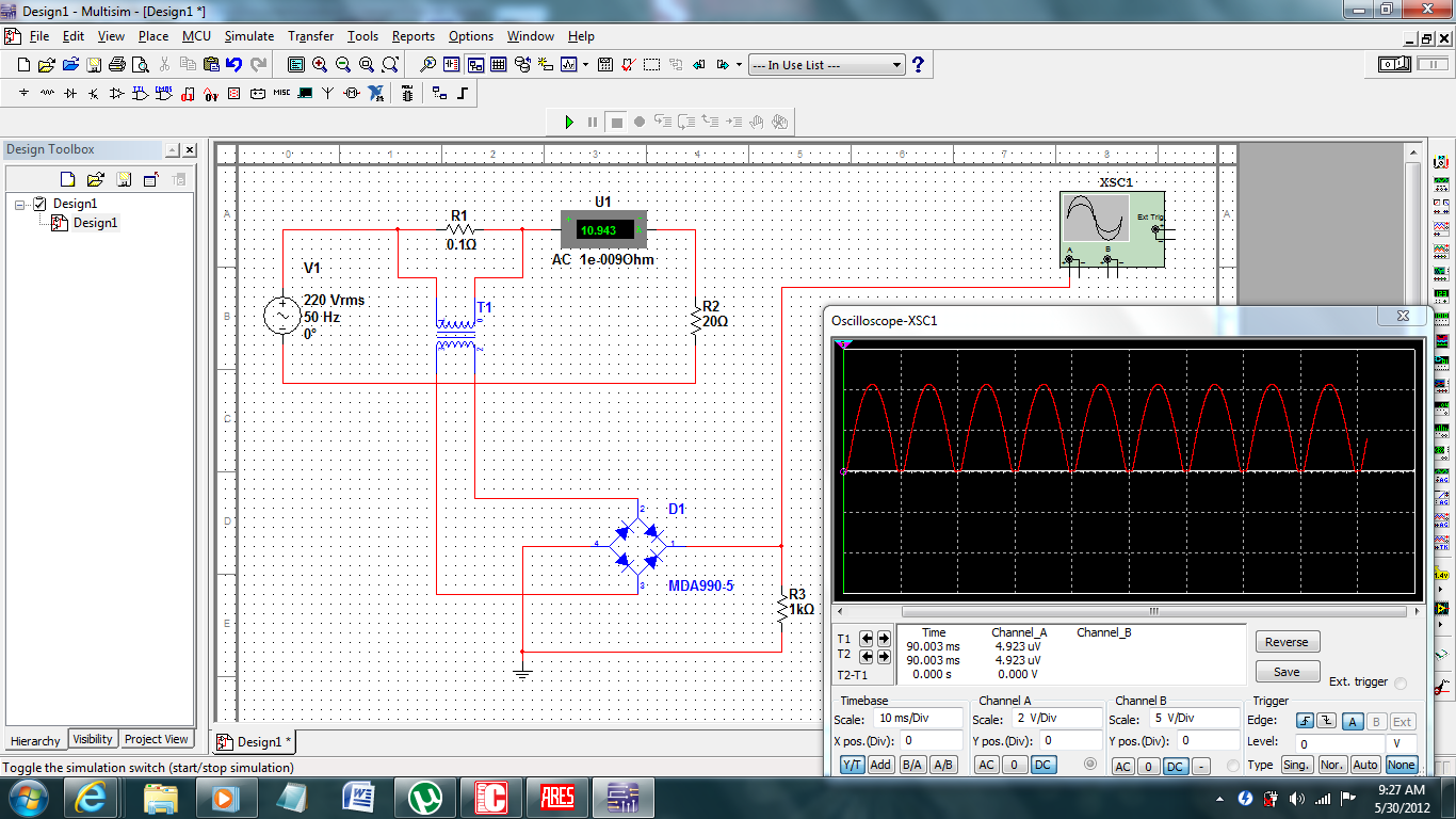
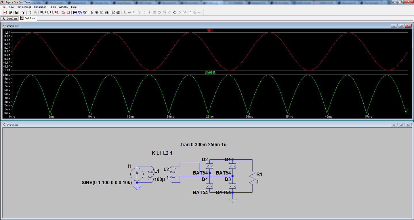
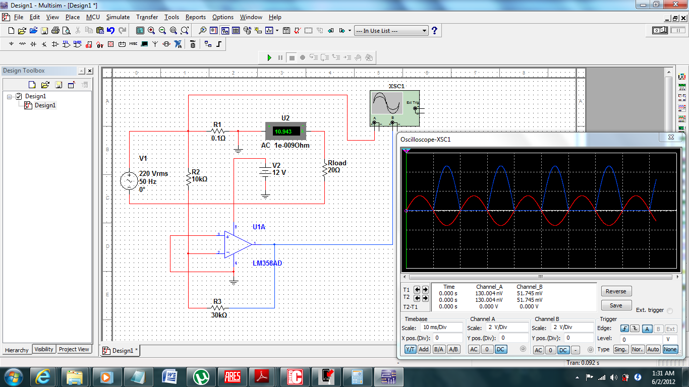
check this out. Is it good idea to meausre AC current. I did a simulation and it went fine and there was a linear change with respect to input.