Continue to Site

Welcome to EDAboard.com

Welcome to our site! EDAboard.com is an international Electronics Discussion Forum focused on EDA software, circuits, schematics, books, theory, papers, asic, pld, 8051, DSP, Network, RF, Analog Design, PCB, Service Manuals... and a whole lot more! To participate you need to register. Registration is free. Click here to register now.

[SOLVED] Intermediate Frequence Transformers (IFT's) in AM radios

Status
Not open for further replies.

pgr2002

Member level 5
Joined
Aug 1, 2013
Messages
87
Helped
0
Reputation
0
Reaction score
0
Trophy points
1,286
Location
Hyderabad, India
Activity points
2,015
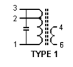
In an AM radio there are 4 types of IFT's viz Red, Yellow, Green, White/Black. could anyone tell or describe the details of these 455 khz oscillators like wire guage (swg or awg), number of turns in primary inclusive of tapping, number of turns in secondary and whether the secondary should be reverse mode or in line with the primary. these IFTs have a small core in which the winding is done and over it a ferrite core is fixed which is screwable for adjustments and these are all enclosed in a mettalic CAN. The primary winding is fitted with a capacitor valued at maybe be 180pf.
 

Attachments

  • IFT diagram.png
    IFT diagram.png
    6.3 KB · Views: 128
Last edited:

Your link did not work for me. As you know the frequency and the tuning capacitance you can work out the inductance of the primary. If you connected the transistor directly to the transformer with the other end going to Vcc, the output impedance of the transistor would damp the tuned circuit , resulting in excessive bandwidth. The collector is taken to a tap on the primary to reduce this effect at the expense of a slight increase of losses in the tune circuit. The base of the next transistor is again a much lower impedance, so between it and the number of turns for the collector circuit, there is a step down ratio of about 4 :1. So one scenario could be primary 200 turns, tapped at 80 for the collector and Vcc, base secondary 20 turns. wire gauge not importent, though primary should be wound with Litz wire. The actual number of turns depends on the ferrite core (or not). The reason for different types is that one could be for the mixer/oscillator, first If amp, second IF amp and detector, all requiring different impedance matching.
Frank
 

Strange, it does not work but if I look it up with google and click on it I get the same adres. Weird ! If you copy the link to google take the first.
Or If you go to electronics-tutorials.amps and select filters (that is how google shows it) you find this page. It has very much info about this sort of transformers.
It includes self -induction, number of turn, ratio, color etc, so all trhe things you look for.

If you measure those transformers with a LCR meter, be sure to do it the right way because of mutual inductance (if they do not have a cap in parallel)
 

Status
Not open for further replies.

Part and Inventory Search

Welcome to EDABoard.com

Sponsor

Back
Top