Continue to Site

Welcome to EDAboard.com

Welcome to our site! EDAboard.com is an international Electronics Discussion Forum focused on EDA software, circuits, schematics, books, theory, papers, asic, pld, 8051, DSP, Network, RF, Analog Design, PCB, Service Manuals... and a whole lot more! To participate you need to register. Registration is free. Click here to register now.

Intelligent battery charger circuit

Status
Not open for further replies.
charger solar atmega

This is awesome charger.

But I'm working with Atmel AVR cpu's. Is posible to share PIC basic code, so I will translate whole project to ATMega and BASCOM AVR?
 
burp charger

pls, anybody done charger for 100 to 200AH SLA batteries using microcontroller especially PIC without those special chips of microchip or avr app notes? i need it seriously. thanks
 

pic charger

hello..
i don,t know how to build the programming.
can u show me the example of the programming.
thanks.
 

Devo proprio realizzare un caricabatterie, appena ho tempo lo realizzo e poi vi dico le mie imprssioni.
 

Hello Dexter Dude
I read all pages about this project''intelegent battery charger'' and I like it and i want to built it,but before I start I have some qwestions?
Can I programm the chip PIC16F628 with PICKIT2 Clone, and how to calibrate the charger with this programmer,I have PIC16F628-04 i/p is need for this chip any crystal?
And finaly what letters are shown on led display and what they mean?
Best Regards macobt
 

I do not own a PICKIT2 Clone( there are quite a few variants ) but if you check your programmer specifications I'm sure you will be able to find out .

This charger uses no Xtal please see schematic on page 4 .

A:" letters are shown on led display and what they mean?"
I already explained that , but here we go
I battery in or just 1 element connected
S slow charge
H high charge
F finish charging and start trickle charging
P Peak error or voltage unmodifed for 10minutes => some error ocured
2 2 elements connected
3 3 elements connected
4 4 elements connected
E A error on accumulator / battery not connected / battery disconected => connection error
 
Hi all,
I put a C Codevision code
It's inspired from Atmel application note with some changes
It's a 3 state PWM FAST charger C code
if anybody is interested I can explain more
It worked good
But The source code isn't just a charger
but the charger part footprint in the code is clear
 

it is the schematic of fast pwm charger I mentioned above
 

Dexter Dude said:
I do not own a PICKIT2 Clone( there are quite a few variants ) but if you check your programmer specifications I'm sure you will be able to find out .

This charger uses no Xtal please see schematic on page 4 .

A:" letters are shown on led display and what they mean?"
I already explained that , but here we go
I battery in or just 1 element connected
S slow charge
H high charge
F finish charging and start trickle charging
P Peak error or voltage unmodifed for 10minutes => some error ocured
2 2 elements connected
3 3 elements connected
4 4 elements connected
E A error on accumulator / battery not connected / battery disconected => connection error
I make it the charger and works,I calibrated by second metod with trim pot,My problem is when I put 2 batteries in charger first he show (I) than goes to slow and high,why he dont show 2 bateries in first place?
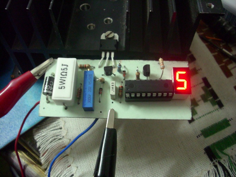
Here is picture of my charger
4672433114_bb5d7f15c8_b.jpg
 

The trim-pot is not corectly calibrated .


Did you use this method :
"The ratio between (Charger output) / Voltage on Pin 17) should be 2.1:1 . So if you have 0.803V on charger output -> adjust Pin 17 to 0.382V " ?
 

I measure the dc voltage on charger output it is 2.85V,and with adjusting the pot(I have multyturn pot of 2kohm,on pin 17 I get between 0.19 and 0.25 volts.
Please help,I realy want this charger to work
Regards maco bt
 

LOSTISLAND said:
it is the schematic of fast pwm charger I mentioned above
LOSTISLAND, can you provide the schematic in PDF, bmp or jpg?
I don't know how to open your file.
Thanks.
 

"" I measure the dc voltage on charger output it is 2.85V" <- I presume the PIC is not in the charger (removed from socket , power is OFF) and you connected 2 batteries o the charger . Then do the following : adjust the trim-pot like this ratio between (Charger output) / Voltage on Pin 17) should be 2.1:1 . So if you have 2.85V on charger output -> adjust Pin 17 to 1.357V .
If by adjusting the trim-pot does not satisfy the above mentioned rule than you probably mounted a diode the wrong way or one of the close components is defective .
 
Dexter Dude said:
"" I measure the dc voltage on charger output it is 2.85V" <- I presume the PIC is not in the charger (removed from socket , power is OFF) and you connected 2 batteries o the charger . Then do the following : adjust the trim-pot like this ratio between (Charger output) / Voltage on Pin 17) should be 2.1:1 . So if you have 2.85V on charger output -> adjust Pin 17 to 1.357V .
.
Hello Dexter
I try again this metod by measuring the dc on charger out and my bateries are 2.8volts,so on pin 17 should get 1.35 volts but I get no more than 0.4 volts on pin 17(Adjusting with pot),I do it this test with PIC out of charger,and I check all components they are OK,can you post once again the hex file for the chip,and to try with first mhetod with hex for calibrating.
I do not know where to find the mistake :(
Please help
 

The hex file is posted on page 4 on this thread . I'v made a picture which might help you to do a proper calibration ( after all ,it's just a voltage divider trouble ). Hope this helps .
Also , double-check your PCB for errors or solder bridges (maybe post your PCB for other users to see ) .

Good luck !
 
I check all parts and there are ok,finaly I check my PIC16F628 and I can read and write on him but anyway I buy a new one and gues what finaly it worked out,I calibrated by first mhetod,I measure the dc voltages when the charger is on,with batery in and without PIC insade,on pin 17 I adjust the desire value 1.35 volts.
Now when I put bateries in it show 2 batery in and it is ok,but with other type of nimh batery its show one batery????
Tell me please it is this explanation with measuring the voltages ok,like I wrote above??
Thanks for helping
Best regards
 

@t said:
LOSTISLAND said:
it is the schematic of fast pwm charger I mentioned above
LOSTISLAND, can you provide the schematic in PDF, bmp or jpg?
I don't know how to open your file.
Thanks.

You could open that with Altium Designer 6 ,
but here is pdf format
 

Your calibration seems to be slightly off .Be sure to follow this rule ratio between (Charger output) / Voltage on Pin 17) should be 2.1:1 .You could adjust the trim-pot in order to increase voltage on pin 17 by 30-50mV .This way the problem battery pack will read "2" instead of "1" . The exact adjustment it is used only by discharging procedure and by detecting the number of batteries attached , charging only uses deltaV so a precise calibrated voltage it is not mandatory .

For a better calibration please use method 2 ( serial connection with PC using an USART adapter like MAX232 or someting similar ) .
 

Status
Not open for further replies.

Part and Inventory Search

Welcome to EDABoard.com

Sponsor

Back
Top