Continue to Site

Welcome to EDAboard.com

Welcome to our site! EDAboard.com is an international Electronics Discussion Forum focused on EDA software, circuits, schematics, books, theory, papers, asic, pld, 8051, DSP, Network, RF, Analog Design, PCB, Service Manuals... and a whole lot more! To participate you need to register. Registration is free. Click here to register now.

Reading constant battery voltage and using the obtained value in sensor formula

Status
Not open for further replies.

anon7548

Newbie
Joined
Feb 22, 2023
Messages
4
Helped
0
Reputation
0
Reaction score
0
Trophy points
1
Activity points
25
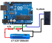
Hi, i am using 3.7~4.2V lithium battery. I am using internal voltage reference to read constant battery voltage as we know that the battery voltage level depletes overtime. The problem is that my sensor (mini solar panel) reads max value under little light and does not go beyond that level no matter how much light falls onto it in the later stage. I need my logic to be <<< if read sensor voltage less than 3V detect night and do something whereas if voltage level is above 3V detect day and go to sleep. The entire project is ready i just need to figure out this.


Code:
void loop() {
 printVolts();
  //REFS1 AND REFS0 to 1 1 -> internal 1.1V refference
  analogReference( INTERNAL);
  //We read A1 (MUX0)
  ADMUX = 0b00000000; 
  DIDR0 = 0;
  // Start AD conversion
  ADCSRA |= (1<<ADSC);
  // Detect end-of-conversion
  while (bit_is_set(ADCSRA,ADSC));
  val = ADCL | (ADCH << 8);
  val = val * 5.7; //Multiply by the inverse of the divider
  Serial.println("val:     ");
  Serial.println(val);
}
 
Last edited by a moderator:

The unloaded PV voltage tends to flatten out at around 0.7V per cell (there may be many cells in series in a single panel) even under low light conditions. As you have noticed, as the light level increases, the voltage rises, hits a limit then goes no higher. It's an electrical phenomenon and nothing in software can avoid it.

The solution is to load the PV so the cells have to 'push' harder and show a better light to voltage relationship. You can do it by wiring a resistor across the panel or if you are trying to conserve the power, use another MCU pin to periodically switch a load on, measure the voltage then switch the load off again.

The light level to output power relationship of PV panels is complicated and the reason why maximum power point tracking (MPPT) is used on larger systems.

Brian.
 

Hi,

I don't understand "... read constant battery voltage...". What does "constant" mean?

You talk about "battery voltage" and "sensor". But in your code I see you only measure "A1" ... whatever A1 is...
I don't see how you can measure two things here (battery and sensor).

How is your variable "val" declared. First you use it as integer, but then you use it a float.

Please give complete informations and draw a flow chart about the problem.

Btw: if you go to sleep, how do you decide to wake up?
Some informatiin about microcontroller type and compiler could be useful, also schematic and some clear comments in your code.
You could put a comment what "val" means or you could use a more descriptive variable name, like "SolarVolt" or "BattVolt".

Klaus

Edit: Corrected "A0" to "A1"
 
Last edited:

Hi,

I don't understand "... read constant battery voltage...". What does "constant" mean?

You talk about "battery voltage" and "sensor". But in your code I see you only measure "A0" ... whatever A0 is...
I don't see how you can measure two things here (battery and sensor).

How is your variable "val" declared. First you use it as integer, but then you use it a float.

Please give complete informations and draw a flow chart about the problem.

Btw: if you go to sleep, how do you decide to wake up?
Some informatiin about microcontroller type and compiler could be useful, also schematic and some clear comments in your code.
You could put a comment what "val" means or you could use a more descriptive variable name, like "SolarVolt" or "BattVolt".

Klaus
Okay, by reading constant battery voltage, i mean, the voltage level should remain constant (same/unchanged)irrespective of what the voltage level is at the battery and yes i am able to read same voltage level.

Code:
float val;
float voltage;
int led = 8;

void setup(){
 Serial.begin(9600);
 pinMode (A0, INPUT);
 pinMode (A1, INPUT);
 pinMode (led, INPUT);

}
void loop() { 
 printVolts();
  //REFS1 AND REFS0 to 1 1 -> internal 1.1V refference
  analogReference( INTERNAL);
  //We read A1 (MUX0)
  ADMUX = 0b00000000;  
  DIDR0 = 0; 
  // Start AD conversion
  ADCSRA |= (1<<ADSC);
  // Detect end-of-conversion
  while (bit_is_set(ADCSRA,ADSC));
  val = ADCL | (ADCH << 8);
  val = val * 5.7; //Multiply by the inverse of the divider
  Serial.println("val:     ");
  Serial.println(val);
  delay(1000);
}
 void printVolts()
{
  int sensorValue = analogRead(A1);
  voltage =  (sensorValue/ val) * 1024.;

delay(1000);
Serial.println(                    "voltage:  ");
Serial.print(voltage);

}

check this, val is the value obtained from battery or battery voltage (A0) and (A1) is reading solar pin
 
Last edited by a moderator:

The unloaded PV voltage tends to flatten out at around 0.7V per cell (there may be many cells in series in a single panel) even under low light conditions. As you have noticed, as the light level increases, the voltage rises, hits a limit then goes no higher. It's an electrical phenomenon and nothing in software can avoid it.

The solution is to load the PV so the cells have to 'push' harder and show a better light to voltage relationship. You can do it by wiring a resistor across the panel or if you are trying to conserve the power, use another MCU pin to periodically switch a load on, measure the voltage then switch the load off again.

The light level to output power relationship of PV panels is complicated and the reason why maximum power point tracking (MPPT) is used on larger systems.

Brian.
I tried using resistor also but unfortunately, i could not find much differences, below i have attached schematic
 

Attachments

  • solar charge.png
    solar charge.png
    162.2 KB · Views: 74

Try a load of about half the PV rating, 45/4 = 22.5mA so the load resistor should be 5/.0225 = 222 Ohms. Use a standard 220 Ohm value and see what the PV voltage on A1 measures under different light conditions.

A word of caution: The PV might produce more than 5V unloaded and in bright light, without a full specification it's hard to tell. It may be rated to produce 5V at 45mA load, in which case it might be more than 5V unloaded and therefore could damage the MCU. For safety, wire a schottky diode from the positive side of the PV to the 5V line on the Arduino board. It will have no effect on the reading but will ensure the PV voltage cant go much higher than 5V and overload the A1 input.

Brian.
Yes, i have used schottky diode for protection
 

Status
Not open for further replies.

Part and Inventory Search

Welcome to EDABoard.com

Sponsor

Back
Top