pathto_teraze
Junior Member level 3
Hi,
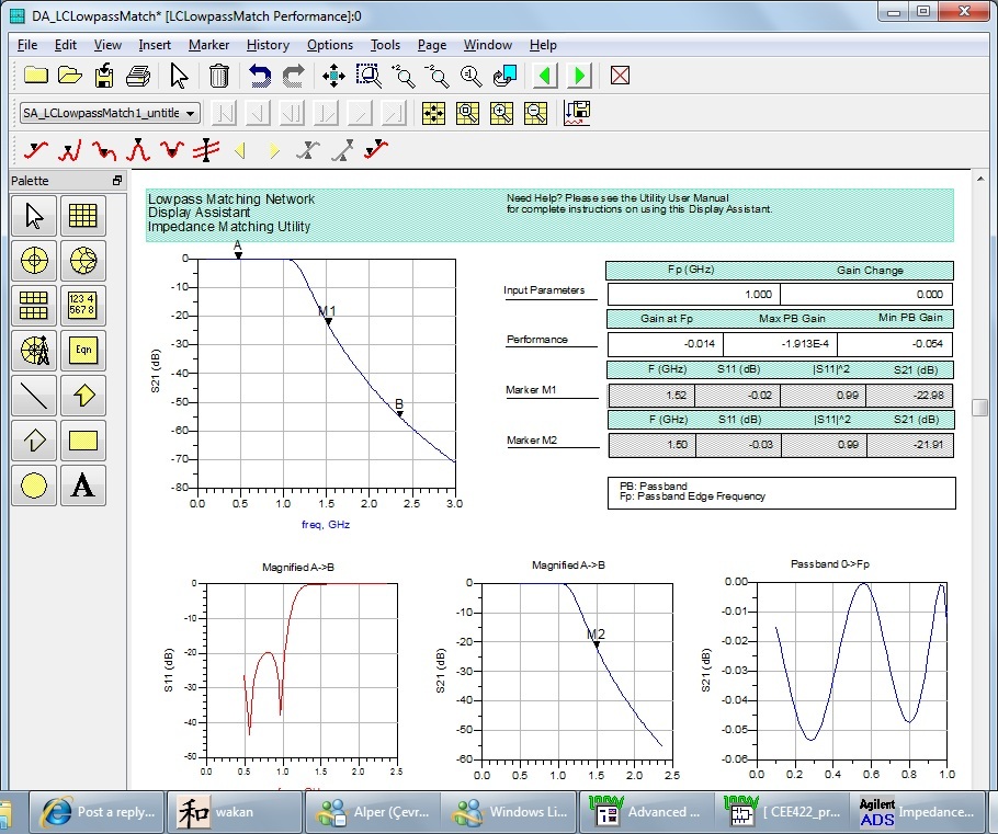
I am trying to solve an impedance matching problem within the bandwidth of [1.5GHz, 2.5GHz]. S(1,1) is required to under -20dB.
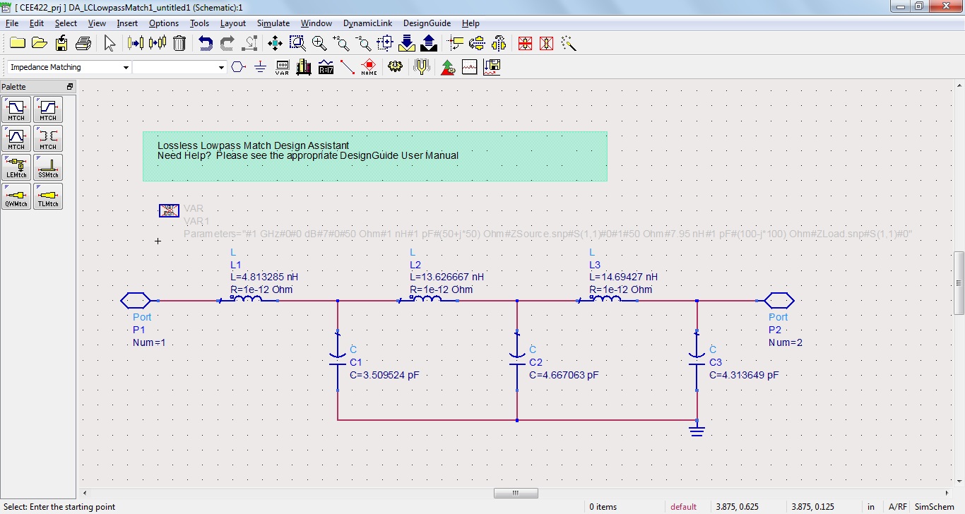
I am using lumped elements to do the impedance matching in ADS.
But I have no idea how to do the impedance matching in a frequency range. I can only do impedance matching in a specific frequency.
Could anybody give me some hint?
Thank you.
I am trying to solve an impedance matching problem within the bandwidth of [1.5GHz, 2.5GHz]. S(1,1) is required to under -20dB.
I am using lumped elements to do the impedance matching in ADS.
But I have no idea how to do the impedance matching in a frequency range. I can only do impedance matching in a specific frequency.
Could anybody give me some hint?
Thank you.