Continue to Site

Welcome to EDAboard.com

Welcome to our site! EDAboard.com is an international Electronics Discussion Forum focused on EDA software, circuits, schematics, books, theory, papers, asic, pld, 8051, DSP, Network, RF, Analog Design, PCB, Service Manuals... and a whole lot more! To participate you need to register. Registration is free. Click here to register now.

igbt goes short circuit

Status
Not open for further replies.
The observations are described rather vague.
- how is the DC bus supplied (e.g. rectifier bridge, lab supply)
- what's the bus capacitor value
- what's the load value
- which modulation is used in test
- what's the kind of change (voltage drop, voltage rise, ripple, high frequency transients) and it's magnitude

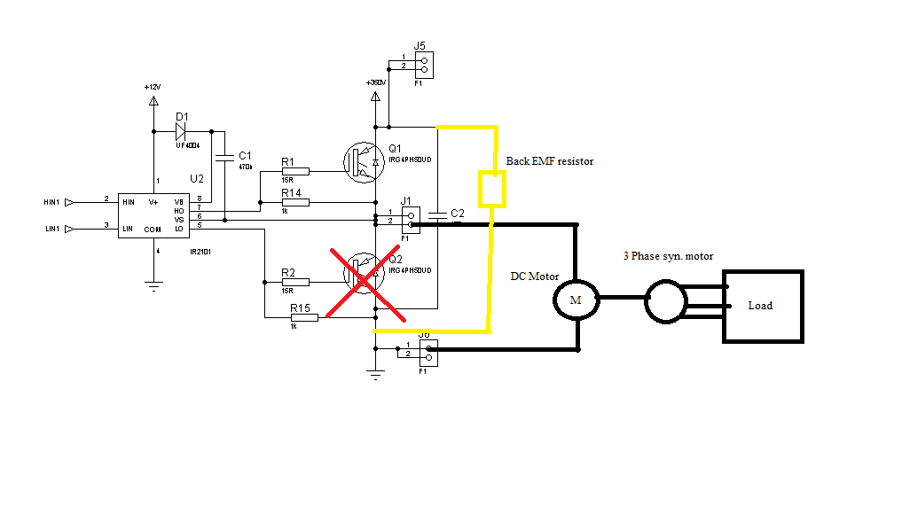
-dc bus is la lab supply
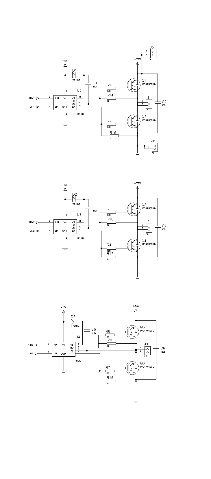
-i connected 100nf capasitor to each pair of igbts ,as can be seen from figure
-i didnt attach a motor but i connected 100 ohm resistor to each output,(i am considering if -the real motor changes something)
-i used pwm by mc3phac by motorola corp.
-the change occours as voltage drops during the switching

i hope they are clear enough
 

At least clearer.

In my opinion, 100 nF is about nothing for a DC bus. You'll get at least some voltage drop by charging the IGBT capacitances. But I don't remember to have heard anything about dead times implemented in your IGBT control, so it may be also a case of cross-conduction ("shoot-through").
 

Hi,
You need to make sure there is no cross-conduction and you need to use a bulk capacitor. In my inverter designs, there were around 150-470uF caps on the DC bus.

Hope this helps.
Tahmid.
 

Hi,if you are very sure that your pwm signal is okay,then simply replace the bulk capacitor with 470uf or above and see what happens,if there is voltage drop again then you have to test each of the igbt.
 

Re: Microwave Oven

i tried some different dead time conditions but nothing changed

i will attach 470uF capasitor to dc bus and try it on monday, thanx for advices i appreciate
if something goes wrong i will be disturbing you again :D
 

Your schematic is correct, so or the actual wiring is the trouble or your driver signals.
The ground for ir2101 is common with the IGBT gnd as in the schematic?
Are the signals in opposite? H1in with L1in ? With switching circuits an oscilloscope is usually needed.
 

hi Tahmid ,

thanx for advice i added 1k resistor each igbt and they work :D

but still there is something wrong,
when i apply pwm signal to igbts the main bus voltage (200V) is changing, whatever i tried i couldnt make it fixed, do you have and advice for this problem too? should i change the capasitors with ones greater capasity

here is the modificated circuit

I am also encountering the same issue may I know what is the wattage rating of the resistor that is used?
 

If you mean, the resistor between gate and source, then use a 1k 0.25 Watt or higher rated resistor.

Hope this helps.
Tahmid.
 
Yes I was refering to the resistor between gate to source.Thank alot!
 

I was refering to the resistor between gate to source
It's O.K. with 0.25W as well. Insufficient resistor rating won't cause bad switching waveforms unless a resistor goes open circuit by total overload. You didn't clarify which exact problem you're observing now. There have been also some previous questions about circuit layout and driving waveforms, that haven't been answered clearly in my opinion.

You previously stated the DC bus is powered by a lab supply. I would expect a stable voltage of a lab supply until the current limit is triggered or reverse power driven to the supply. What's the DC current in idle state and with drive signal activated? How about the said 470 uF capacitor?

P.S.: Do still have the 100 ohms resistive load? It would cause a considerable load current with higher PWM duty cycles. Any change if you disconnect it?
 
Last edited:

Hi Tamid! Alright the short circuit problem is solved however there some issues with the microcontroller. The microcontroller shall auto reset itself and I do not have much idea why this problem occurs.The operation of my micro controller initially starts to increase the pwm duty cycle but when I start to decrease the duty cycle abit, it shall auto reset itself or hung at a fixed pwm duty cycle.Can anyone advice to get about it? thanks

weirld problem solved never to put micro controller too near to the dc supply(with transformer). Not really sure probably the magnetic waves produced corrupt the microprocessor
 

20_1299593984.png


Help needed again. Okay now i am working on controlling a DC motor (prime mover) connected to the 3 phase syn motor so as to control the frequency. Alright, currently i can control the dc motor speed without any problem like the speed of 3000rpm or 1500rpm with the class c chopper(pwm) but whenever i turn on the variable load connected to the syn motor like 0 to 400ohm, immediately the dc motor slow down and the mosfet at the low side shall break down as shown in the picture. I am not sure what is the cause of the problem. Is it the back emf but i did connect the resistor to dissapate the back emf? The dc motor is draw approximately 230V 2-4A and my mosfet(IXTN36N50) rating is 500V 36A and operating at 4khz (too slow?), dead time for pwm is 4us. Even without changing the pwm signal duty cycle leaving it constant like 92%, the dc motor is still able to run but whenever load is applied to the synchronous generator, the low side mosfet still fails and breakdown.:sad:
 

The load you put on the 3 phase machine mechanically loads the the DC motor and in turn causes more current to be drawn by the Dc motor? If this is the case there will be more current free-wheeling in the internal diode of Q2 when Q1 turns on, if Q1 turns on too fast the dv/dt applied to Q2 can cause it to turn on briefly (by gate rise (due to capacitive coupling of the dv/vt to the gate) due to the 15 ohms being too high to keep the gate below threshold).

If you are using a mosfet (IXTN36N50) instead of an IGBT as in the drawing then high applied dv/dt can trigger the internal xtor in the mosfet, which generally latches on catastrophically.

Solution: either have a negative 5V (or more e.g. 15V) on the gate drive to Q2, or have an npn,pnp emitter follower between the IR2101 and Q2 gate with a 15R turn on (in the emitter of the npn) but a 0 ohm turn off (in the emitter of the pnp), this to ensure the gate does not rise above 1V when Q1 turns on.
solution #2, use an IGBT (with diode) instead of a mosfet as they have lower capacitive feedback effects.
Hope this helps, Regards, Orson Cart.
 
Last edited:

Unintended turn-on by dV/dt would be a plausible explanation, but there are many others as well, e.g. corruption of control circuit or gate driver input signals by transients generated in the power stage (similar to the previously reported uC reset problems). This would be mainly a problem of unsuitable circuit layout, grounding scheme etc.

I would try to operate the output stage with a light load where it's still safe, and check all involved waveforms thoroughly with an oscilloscope. Reasonable probing may be a problem however, usually differential probes are required to get true waveforms unaffect by common mode voltages.
 
  • Like
Reactions: MRAMA

    MRAMA

    Points: 2
    Helpful Answer Positive Rating
check your death time to prevent short circuits
 

The reason you don't get it work is that you have connected the IR2101 as you would do with a IR2111. Look at the datasheet for IR2101, and you will see that you get a short.

To solve the issue, use a IR2111 instead.
 

Look at the datasheet for IR2101, and you will see that you get a short.
Which schematic are you referring to? Post #27 is correct, corresponding to the datasheet. The snippet shown in post #33 isn't different.
 

Which schematic are you referring to? Post #27 is correct, corresponding to the datasheet. The snippet shown in post #33 isn't different.

I may read over something or otherwise be wrong. I just tell what the datasheet says.
When that is said - the datasheet never explicit tell that the configuration above is wrong. I put a drawing to show what I mean.

Image is snipped from post #27.
 

Attachments

  • compareWirings.png
    compareWirings.png
    40.3 KB · Views: 156

I already guessed you are referring to this point after seeing the datasheet.

The IR201 datasheet drawing is obviously messed up. A bootstrap driver would never work with a load connected between low-side collector and high-side emitter node, because the emitter node needs to be pulled to GND repeatedly.

P.S.: The important difference between IR2101 and IR2113 is the separated logic supply of the latter, which allows to drive it with a logic voltage and offers some noise tolerance.
 
Last edited:

Status
Not open for further replies.

Similar threads

Part and Inventory Search

Welcome to EDABoard.com

Sponsor

Back
Top