Continue to Site

Welcome to EDAboard.com

Welcome to our site! EDAboard.com is an international Electronics Discussion Forum focused on EDA software, circuits, schematics, books, theory, papers, asic, pld, 8051, DSP, Network, RF, Analog Design, PCB, Service Manuals... and a whole lot more! To participate you need to register. Registration is free. Click here to register now.

How to reduce DC a bit without resistor or capacitor? Is there a simple solution?

Status
Not open for further replies.
Good point! That was one of my questions this morning. Yesterday night I was too tired. :) Thanks for the good point!

- - - Updated - - -

godfreyl,

Thanks for pointing this out. I was meaning to ask goldsmith about it, but was tired yesterday and left this for this morning.

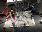
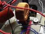
I have 8 LED drivers working on 4 strings of LEDs. Each string uses 300mA of current, so I use 2 LED drivers per string. I simplified the schematics here to focus only on the suppressing extra 32V. :)

As to heat dissipation, I use a heat sink on all of the LED drivers. Usually if they heat, they begin to lower the LED current. With the heat sink, the current stays constant.
Actually I might even put 3 of them per string to spread out the current among them, so I might not even need the heat sink at all or will need a very small one. :) Gotta try it tonight.

Actually I need an output of 108V. I need to eliminate extra 32V with his buck converter. I will ask him this questions tonight, when he comes online. :) Good attention to details! :)

Steven
 

sabouras,

Tried that. It does not work for me, because brightness of LEDs drop. And if I remove the resistor, peaks on LED drivers exceed 45 volts allowed. :-(

Steven
 

Hi again
What is happened here ? :?::grin:

Actually I need an output of 108V
You should mention it at first .
Well no problem if you need only 108 volt as vout you should change the UC3844 with a driver which can deliver more variations of duty cycle . and also using some elements with ability of accepting higher voltages .
But if you try to change your LEDs i think it would be better . i mean if you could do something like using composite arrangement (some leds in series and then in parallel with another chain ) thus it would be better because working with that voltage is a bit dangerous . if someone by an accident touch that , voltage it can be very harmful .
What i want say is you can increase current instead of increasing voltage , ( with changing arrangement of LEDs ) . for my opinion if you can do it , it would be better . isn't it ?
If you can you don't need to change the buck circuit , what you need is only changing some little changes in feedback resistors !
Best Wishes
Goldsmith
 

Goldsmith,

Here is what I was able to catch from the drawing you sent me. Would you kindly check if I got the values right? Also, I am correct to assume that this buck converter will eliminate excess of 32V? I ned the output to be 108V, but I have noticed that the output on your drawing states 32V. Please clarify.

Steven

new.PNG
 

You could also use a thirystor and a LM555 or something similar in order to achive the voltage and the amps you need. I suspect it may need PWM pulses and may need a zero crossing detector. The simple diode reduce at half the current and the voltage. You must put after the diode a capacitor which provide the power you need until next period occurs.
 

Here is what I was able to catch from the drawing you sent me. Would you kindly check if I got the values right? Also, I am correct to assume that this buck converter will eliminate excess of 32V? I ned the output to be 108V, but I have noticed that the output on your drawing states 32V. Please clarify.
Hi Steven
Did you read my former post #23 precisely ? if so , i've asked some questions about your design which can be resulted in better response of your circuit , so can you answer them ?

and another question is why you've used those current regulators in series with your LEDs ? if you tell me a bit more about what you are trying to do , perhaps i can help you to yield better result ? are you attempting to turn many LEDs on and supply them from main power line directly ? is that the idea ? if so i don't think those current regulators would be required . or perhaps i'm in wrong consideration and aim behind this project is different than i could understand ?

Anyway , C6 is not 200 F ! it is 200 or 220 uf ! and R4 is not 1 ohm it is between 10 or 6.8 ohm . and polarity of D3 should be reversed .
A question : why you've used a 3 mega ohm resistor and a 50 k ohm resistor to provide the required voltage for integrated circuits ? that is not a good idea ! why R5 is 6.2 k ? it should be 10 k .
With all of these considerations the circuit will give you only 32 volts in out put . as you've forgot to answer my questions in last page before i start to design ! i thought you need 32 volts .
If you want the i could help you as well , so please try to answer my questions in this post and my former post before this . ok ? thus i can help you more and of course perhaps in better way .

Best Wishes to you
Goldsmith
 

Goldsmith,

Sorry, I did not get E-mail notifications about your replies, as I did in the beginning...

Here are the answers to your questions.

The reason I need 108V is that I have pre-assembled LED circuits that I must use. Sure, it would be better to use lower voltage and higher currents, but it would not work for me.

I used those LED drivers simply because I did not know any others. Key was the simplicity.

In my next design I would need to light up about 1200 LEDs on a single panel. There I would have to keep voltage high (250V perhaps) to keep the current relatively low, so cables are not that thick.
So, I am bound to work with high voltages. And I would need to find a better driver and better circuitry.

As to 3Mom resistor - I tried to calculate the current needed to feed both chips (based on 108V design). One chip needs 200mA and the other one 11 mA to operate. So, if I use these resistor values I would be able to supply current needed.
As to resistor R5, I thought it was 1k, so I re-calculated its value (for 108V instead of 32V). Now I need to re-calculate it again. :)

Sorry, I got confused.... I thought that every time some posts a reply, E-mail comes to notify me...

Steven
 

The reason I need 108V is that I have pre-assembled LED circuits that I must use. Sure, it would be better to use lower voltage and higher currents, but it would not work for me.

I used those LED drivers simply because I did not know any others. Key was the simplicity.
Hi Steven
Ok so now you will need some changes in your circuit to obtain 108 volt as vout . ( it is not hard ! )
In my next design I would need to light up about 1200 LEDs on a single panel. There I would have to keep voltage high (250V perhaps) to keep the current relatively low, so cables are not that thick.
so if you need to use them in series as you mentioned before then you will need to increase the voltage of power line because as i know out let in the U.S is about 120 volt , and if you need 250 volt you will need to use a flyback or forward converter . but here is a big risk factor . because while you're using Leds in series together , it is possible that one of the LEDs being destructed by an unknown accident or by passing the time . if such a problem being occurred then all of the LEDs which are in series together will be turned off .
Anyway
And I would need to find a better driver and better circuitry.
You can easily use TOP integrated circuits which have been designed for compact applications . they can easily being used for a forward or flyback converter .
Sorry, I got confused.... I thought that every time some posts a reply, E-mail comes to notify me...
I see , unfortunately this problem is happening for me too ( of course sometimes but not every time ! so most of the times i prefer to check here )
Ok now you need to change value of elements as this :
You will need to replace the UC3845 with TL594-D . it can deliver higher duty cycle in out put with an specific configuration . or any other PWM driver with the same abilities . however it is possible to increase duty cycle of UC3845 too but it is not a good idea to force it !
The electrolytic capacitor which is in out put : two 100 uF capacitors in parallel together with voltage rating of 160 volt or higher .
Out put inductor : 974uH ( don't forget to use a gaped core for it ! )
And Feedback resistors should be changed too . Vout = Vref(1+R1/R2 )

Good Luck
Goldsmith
 
  • Like
Reactions: tpetar

    tpetar

    Points: 2
    Helpful Answer Positive Rating
Goldsmith,

I have been thinking a lot about how to organize LEDs for these 1200-strong panels. Ideally, I should keep them in short strings, so if one LED is out, only a small portion of LEDs are out. However, then I would need dozens of strings to feed. The power supply is meant to be a separate unit. if i need to bring dozens of wires to the panel, it would be very bulky and cable would cost me a fortune. I cannot put power supply on the panel, because panel will be very hot and because it will add size to it (and it suppose to be quite slim). So, the only reasonable thing that I came with is to keep 5-6 lines of LEDs and feed them with a high voltage.

If you have a better idea, I would love to hear you.

You mentioned TOP integrated circuits. I have never heads of that abbreviation. What does TOP stand for?

Now, as to the inductor. You said that it should be gaped care. May I kindly ask you why is it important?

I will do some work on schematics today and will present for your review/approval tomorrow. :)

Thank you for taking your time helping me! Unfortunately, I do not have any friends who would be interested in electronics... :-(

Steven

- - - Updated - - -

Goldsmith,

I am having a hard time locating an inductor with the gap in the core. I assume it should be a ferrite core since the buck converter will operate on 100-300 kHz frequency (am I right?). Inductors that Digikey or Mouser sell do not have anywhere in their datasheets an information if the cores have gaps. What would you suggest?

Steven
 

I have been thinking a lot about how to organize LEDs for these 1200-strong panels. Ideally, I should keep them in short strings, so if one LED is out, only a small portion of LEDs are out. However, then I would need dozens of strings to feed. The power supply is meant to be a separate unit. if i need to bring dozens of wires to the panel, it would be very bulky and cable would cost me a fortune. I cannot put power supply on the panel, because panel will be very hot and because it will add size to it (and it suppose to be quite slim). So, the only reasonable thing that I came with is to keep 5-6 lines of LEDs and feed them with a high voltage.


Hi Steven

How told that you need to use gang of wires ? the PSU will have only two wires . your module can be used as multi wire easily ( with the proper design of PCB ) so you can easily use them in parallel . that's all and easy .


You mentioned TOP integrated circuits. I have never heads of that abbreviation. What does TOP stand for?

TOP integrated circuits are pretty useful materials which have been designed for people which are not so familiar with SMPS design or perhaps for somebody that likes to have a compact design .
Please try to find datasheet of TOP261EN/YN . and read it's datasheet and applications precisely then you'll get what i mean .
Now, as to the inductor. You said that it should be gaped care. May I kindly ask you why is it important?
Gaped core ? yes certainly . if you look into the inductors more precisely , you'll see when you are trying to lead current through them , the magnetic molecular groups will be formed in one side and their effect will be summed together . but it won't be like here anymore ! it means when you increase the current , it is possible that those magnetic molecular groups became formed ( all of them ) so there is no one lese to being formed and it is the start time of bad effects . it means current through the inductor will be distorted and bad harmonics will be provided . for more information you'll need to take a look into magnetic analysis books season of inductors and saturation in core .

To avoid our core being saturated we'll need to add a gap space , so the reluctance will be increased ( Req core = Rgap+Reluctance ) so then , because Rgap is nearby infinite then the saturation won't be happened easily and it will guarantee that our core and our inductor both are linear devices .
Thank you for taking your time helping me! Unfortunately, I do not have any friends who would be interested in electronics...
But now you can have !!! ( you and i can be friends together ha ha ! ) :grin:


I am having a hard time locating an inductor with the gap in the core. I assume it should be a ferrite core since the buck converter will operate on 100-300 kHz frequency (am I right?). Inductors that Digikey or Mouser sell do not have anywhere in their datasheets an information if the cores have gaps. What would you suggest?
your buck converter will work at 100 KHZ so the current though the inductor will be like that ( a triangular current ) . most of the times i wind my own inductors . so you can wind them too . then you can create gap in the core as well . for example PQ series or EE cores are fantastic for this issue .


Best Wishes to you
Goldsmith
 

Goldsmith,

Let me work on the schematics first then I will focus on the inductor. I used to make make transformers when I was a teenager. Lots and lots of them... :) I used to live in Russia back then and all power supplies were linear. :)

Steven
 

Let me work on the schematics first then I will focus on the inductor. I used to make make transformers when I was a teenager. Lots and lots of them... I used to live in Russia back then and all power supplies were linear.
Hi Steven
Ok , while you're working on schematic if you stuck on something , you can ask me again . :wink:

Good Luck with your schematic
Goldsmith
 

Hi Steven, I clearly am not in the league with your other helpers, but here goes: 1 solution: use a zener diode and a resistor as a simple regulator, yes simple, yes there will be heat dissipated. To spread the heat(and current) set one up for each string. 2 solution: Use a transformer in your power supply. You should be able to find one that will get you close after rectification. 3 solution: Add more LEDs to add up to your 168VDC.(current would be the same in each string). 4 solution: drop a zener in each leg(in series with the LEDs) to bring each leg down(32 V zener).
No matter which of the methods you use, mine or theirs, when you reduce voltage with current involved, you will have heat, a little on several parts or a lot on a few parts.
Good Luck,
Rick
 

Thanks, Rick!

I know of these solutions, but I was looking for one where there is little heat dissipation. I really like what Goldsmith proposed. I had a chance to examine another buck converter yesterday and was impressed. This is a really flexible solution. Once you know how to build one, a totally new opportunities open up.

Steven

- - - Updated - - -

Goldsmith,

I got stuck with a lot of work here and had no time to work on schematics. But I am not a quitter, just busy at work. Hopefully will have more time in a day or two. :)

Steven
 

Goldsmith,

I had a day off yesterday and I did some research on LED drivers. I came up with what I believe would be a better schematics. Here it is:

candidate2.PNG

This is a typical LED driver schematics that came off datasheet 1 of this IC (attached). I built it today, but it does not work well (flickers). Therefore, I have a few questions for you, if I may.

1) When I started the boost converter, light began to flicker, then they were off, came on again, flickering, etc. The signal that went from the IC to MODFET changed its shape. First it had more duty (it was on most of the cycle, switching off for a short moment), then the duty has changed. The signal on the gate begins to be off most of the time with short ON spikes. Does it mean that MOSFET drained too much current from the IC? Should I increase the resistor R4's value? Finally IC died (with the smoke) and MOSFET died (internally open). I am puzzled as to why...

Initial signal (no load):
013.JPG

2) Finally, how do I supply IC with 15V? How do I convert high DC voltage (120V) to lower DC voltage without transformers? I might be repeating myself (we were working on the buck converter earlier), but I am not sure if I can get the necessary voltage via resistor divider. How usually it is done?

Hope I do not trouble you too much. :)

Steven
 

Attachments

  • 014.JPG
    014.JPG
    3.2 MB · Views: 71
  • 015.JPG
    015.JPG
    2.3 MB · Views: 79
  • datasheet 1.pdf
    1.7 MB · Views: 52
  • datasheet 2.pdf
    1.1 MB · Views: 72
Last edited:

1) When I started the boost converter, light began to flicker, then they were off, came on again, flickering, etc. The signal that went from the IC to MODFET changed its shape. First it had more duty (it was on most of the cycle, switching off for a short moment), then the duty has changed. The signal on the gate begins to be off most of the time with short ON spikes. Does it mean that MOSFET drained too much current from the IC? Should I increase the resistor R4's value? Finally IC died (with the smoke) and MOSFET died (internally open). I am puzzled as to why...

Hi Steven
how are you ?
The IC that you've used for boost converter is not good enough ! you can easily use uc3845 which has only 8 pins ! for this aim as a boost converter with current protection too . for many of the LEDs !
For the reason , you can test these things :
remove the C7 and watch what's going on . is still the problem available ?

show me the voltage across the R1 ! it can be also the cause ! if it is relax you have to optimize it ! show me the waveform with load and without load . ok ?
how do I supply IC with 15V? How do I convert high DC voltage (120V) to lower DC voltage without transformers? I might be repeating myself (we were working on the buck converter earlier), but I am not sure if I can get the necessary voltage via resistor divider. How usually it is done?
You have many of the ways ! for instance using the AC path and using a capacitor as it's XC mode to decrease the voltage and then a zener diode thus you can supply the IC as well . or perhaps using a simple oscillator to supply it . do you know what i mean by oscillator here ?

Hope I do not trouble you too much.
Don't worry about it :-D it is ok !

Best Wishes
Goldsmith
 

Goldsmith,

I do not understand completely how uc3845 operates. I only have seen similar IC in fly-back design. Is that how you propose to use it? If not, I'd like to hear more about it.

Here is an update to my question and results of the steps you proposed:

Removing C7 did not change anything. It looks like there is a lot of noise in lines when conductor works.

Ok, here is what goes on the inductor. See how dirty the signal is? Could it be because my components are not close to each other and have quite long wires between them? When I moved them a bit closer to IC, I have noticed the reduction of that interference.

1.png

This is the current through MOSFET.

2.png

And this is the current to the diode.

3.png

Current/voltage on resistor R1:

4.png

This is what IC sends to MOSFET:

5.png

This is the signal it measures:

6.png

This is what comes out of the diode with the load (all previous measurements are with the load too).

7.png

This is what comes out without the load:

8.png


This is how I imagine using the capacitor and zener diode. Is that what you had in mind?

Capture3.PNG


As to oscillator, I am not sure how you propose to use it...


Steven
 

Hi steven
Sorry for the delayed reply . it was some days that my internet had some problems ,
Anyway
I do not understand completely how uc3845 operates.
May i ask you why ? which section is unclear to you ? UC38XX series have good datasheets and application notes which easily cover the idea of how they are working and how to use them in designs .did you see them ?
I only have seen similar IC in fly-back design. Is that how you propose to use it?
I have a funny idea ! when a circuit or a thing can deliver PWM signal we can use it for all kinds of SMPS ! it is really simple . so that driver can be used for flyback or h bridge or half bridge or push pull or ... etc
Ok, here is what goes on the inductor. See how dirty the signal is? Could it be because my components are not close to each other and have quite long wires between them? When I moved them a bit closer to IC, I have noticed the reduction of that interference.
You didn't show me the voltage across the inductor ! however it is not important for this moment of time because it is clear !
Your inductor and your mosfet and your capacitor should be very close together . long distances can easily destroy the result . ( this rule is applied to the all kind of switching circuit which is dealing with high frequency of operation )
Steven ? did you really use BSV81 for your mosfet ?! and may i ask you why you have used it ? according to the what criteria ? because it is not good for this aim . as i saw it's datasheet , it is for low powers and it is not also a mosfet ! it is a fet . and it's voltage and current ratings was not good when i saw it . and it's Rdson is not good too . why you don't use IRF740 ? i think then the result can be as it is supposed to be . test this mosfet and let me know the result . ok ?
This is how I imagine using the capacitor and zener diode. Is that what you had in mind?
Sorry but no it isn't what was in my mind :wink:
What i told was this : a capacitor in AC path ! but you have used it in DC path , so after 5 time constant that capacitor will be open circuit and won't allow any current go through itself !
so use it in AC path and before you connect it to your main circuit test it independently and if the result was ok then you can connect it to your circuit . ok ?
As to oscillator, I am not sure how you propose to use it...
About an oscillator i mean you can use a simple LC oscillator which can oscillate on high frequencies and then size of the inductor or transformer will be so small . and then twist some turns on core of the inductor and then it will deliver you a low voltage that you want and you can recfity and filter it and use it ( it is what is happening on some kind of chargers ! )
If it is unclear i can draw something for you .
Best Wishes :wink:
Goldsmith
 

Dear Goldsmith,

I learn well on real life examples. When I read the datasheet of UC3845, it gets frustrating (what is error amplifier? Why do I need one? How is it used? What is PWM latch? What is a clamp?). Is there any way you could simplify it for me please? Most of the datasheet is close to the foreign language to me. :-(

I have a dream of being able to build various circuits (see below) and being able to calculate values for various loads. Can you help me with that? :)

DC-DC.PNG

It took me 2 days and a handful of burnt MOSFTS and ICs to figure out that an inductor and MOSFET should be close to each other. :))) What is easy for you was a 2-day struggle for me. :))) Is it important what end of the inductor is connected to a MOSFET (beginning or end?). Is it important what kind of gap does it have? Is it important the physical structure of the inductor (bobbin-type vs. transformer type vs. donut-type)? How can I test an existing inductor to see if it works for my application? My goal is to find a source for inductors to buy, not to make them myself (because I want to create a bunch of those).

As to MOSFET, the one on you are referring to is no longer used. I figured out that it was a low voltage tyope (that is why they all died on me). So, I experimented with a bunch of different types, ending up with 5N50FT (because of its low capacitance, which I do not know if important or not).

As to the power to IC, I realized that I did not do it correctly. However, I cannot figure out how to do it right. Maybe like this:

Untitled-1.png

As to oscillator - yes, I'd like to see what you are talking about. :)

Steven
 

Hi dear Steven
How are you ?
first of all let me confess that since some days ago my internet connection had some problems and after some problems i could improve it and now it is better . ( it is impossible that i answer a question so late ! )
So sorry for the delayed reply .

Anyway
I learn well on real life examples. When I read the datasheet of UC3845, it gets frustrating (what is error amplifier? Why do I need one? How is it used? What is PWM latch? What is a clamp?). Is there any way you could simplify it for me please? Most of the datasheet is close to the foreign language to me.
Dn't worry about it . i will write some pages about how to use UC3845 driver and i will send it to you very soon . then you will be able to use it simply .
I have a dream of being able to build various circuits (see below) and being able to calculate values for various loads. Can you help me with that?
Certainly . i can introduce you some books if you want . some books which are dealing with those things .
It took me 2 days and a handful of burnt MOSFTS and ICs to figure out that an inductor and MOSFET should be close to each other. )) What is easy for you was a 2-day struggle for me. ))
When i'm saying something is easy because i've did it for many times . and i could earn experience . so what you have did is called a good and practical experience . so that is just ok . and a usual process of learning ! a friend of mine told me something ! he told me make circuits and make mistakes and then learn from your mistakes . thus you'll learn so much !

Is it important what end of the inductor is connected to a MOSFET (beginning or end?)
If you are talking about inductor , let me say no . it is not important . but if you are talking about coupled inductors or as a matter of fact transformers , yes it is important ! but in your case which certainly is a usual inductor no it is not important .
Is it important what kind of gap does it have?
Yes it is important . gap will be used to create enough reluctance to prevent the core being saturated . and it's size is important . but most of the times calculations of GAP is so time consuming and complicated . so to prevent wasting the time i use trial and error and some rules of thumb to determine it . and all of the times it worked well .
Is it important the physical structure of the inductor (bobbin-type vs. transformer type vs. donut-type)?
I suspecting that you are referring to the shape of the core . for instance pot core or toroidal core or PQ series core or ... etc . in these cases no it is not important .
How can I test an existing inductor to see if it works for my application?
Easily ! you know name of the core of your inductor . you can refer to the datasheet or tables of core selection ( if you are not familiar with them i can give you these tables . ) and then you can judge if the core is suitable or not . after that the size of wire ! you can anticipate something ! if it is good or not according to the frequency of operation and skin effect and value of current through it .
As to MOSFET, the one on you are referring to is no longer used. I figured out that it was a low voltage tyope (that is why they all died on me). So, I experimented with a bunch of different types, ending up with 5N50FT (because of its low capacitance, which I do not know if important or not).
LOW ciss for mosfets can be so good but not very low ! because mosfets with very low CIss are more expensive in compare with usual ones .
even Ciss is higher then required gate instantaneous current will be higher which is not so important in most of the cases .
so you can use better mosfets .
As to the power to IC, I realized that I did not do it correctly. However, I cannot figure out how to do it right. Maybe like this:
About the picture in red which you have attached above it is still wrong ! because still the current through the capacitor is DC ! why ? because the ground of bridge rectifier is coming from the diode ! so it is DC and capacitor can not do it's best . ok ? so use it in complete AC path !
As to oscillator - yes, I'd like to see what you are talking about.
Regarding the oscillator i can show you this :
oscillator.JPG
Can you predict how it is working ?

Best Wishes to you
Goldsmith
 

Status
Not open for further replies.

Part and Inventory Search

Welcome to EDABoard.com

Sponsor

Back
Top