Continue to Site

Welcome to EDAboard.com

Welcome to our site! EDAboard.com is an international Electronics Discussion Forum focused on EDA software, circuits, schematics, books, theory, papers, asic, pld, 8051, DSP, Network, RF, Analog Design, PCB, Service Manuals... and a whole lot more! To participate you need to register. Registration is free. Click here to register now.

How to reduce DC a bit without resistor or capacitor? Is there a simple solution?

Status
Not open for further replies.

stevenmahoney

Junior Member level 3
Joined
Mar 11, 2013
Messages
30
Helped
0
Reputation
0
Reaction score
0
Trophy points
1,286
Visit site
Activity points
1,590
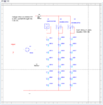
I have a simple schematics with a number of LED drivers. LED strings have a certain number of LEDs that I cannot change. In order for LEDs to operate properly, I have to feed them with 108V and 1.3A current (combined).
If I rectify 120V after diode bridge voltage increases to approximately 168V. I have excess of 32 volts (28V drops on LED drivers).

I can use a resistor or a capacitor (on AC side) to get rid off excess of 32 volts, but both are bulky (and in case of the resistor hot) solutions.

Is there any other smarter way to solve this problem? Any ideas will be appreciated. :)
1.png

Steven
 

I have a simple schematics with a number of LED drivers. LED strings have a certain number of LEDs that I cannot change. In order for LEDs to operate properly, I have to feed them with 108V and 1.3A current (combined).
If I rectify 120V after diode bridge voltage increases to approximately 168V. I have excess of 32 volts (28V drops on LED drivers).

I can use a resistor or a capacitor (on AC side) to get rid off excess of 32 volts, but both are bulky (and in case of the resistor hot) solutions.

Is there any other smarter way to solve this problem? Any ideas will be appreciated.
Hi Steven
You have many choices . one of them is designing a simple buck converter which is very efficient in compare with a resistor ! if isolation is required there is another option ! using a TOP integrated circuit and designing a forward or fly back converter based on that .
Best Wishes
Goldsmith
 

Hmmm. Buck converter? Let me look into it... Do you happen to have like a simple schematics for me to chew on?

Steven
 

Hmmm. Buck converter? Let me look into it... Do you happen to have like a simple schematics for me to chew on?
Hi Steven
It depends on what is simple for your opinion :wink:
Most of the times i prefer how to design something instead of giving all of the circuit .
For example it is a good idea to use a UC3845 to create PWM and then a float driver like IR2117 which has been designed for h side .
If it is not clear i can draw a schematic for you !

Best Wishes
Goldsmith
 

Goldsmith, I am trying to figure out what this circuit would do for me. I looked at the datasheet and it looks like IR2117 is driver for MOSFET or IGBT. If either of these transistor would be driven by IR2117, the output will be a square wave, right? Surely, output transistors will not be used instead of resistor to convert excess voltage in heat. Then what would it produce? How would it be used to limit the voltage? :)

What would be the general idea? :)

Steven

Unless... it will be used with the inductor in that buck converter you've mentioned... :)
 
Last edited:

the output will be a square wave, right?
Steven ,
Not without input ! IR2117 is a power switch driver . if you give it a square wave ( it is what you should do ) thus it will turn on or off a mosfet or an IGBT .
Surely, output transistors will not be used instead of resistor to convert excess voltage in heat. Then what would it produce? How would it be used to limit the voltage?
Here a simple lovely trick has been used ! ha ha ! out put will be a square wave with amplitude of input for instance 169 volts . but you won't apply it into your load directly . a low pass filter with a diode will be used then it will take average from it so the voltage will be reduced as you want . for reducing or increasing the voltage you can change the duty cycle of your wave .
But it needs a feedback loop which will be provided by uc3845 . i.e : uc3845 will provide PWM and some kind of feedback ( current fed and voltage fed )

I think you've got the idea , isn't it ? :idea:
 
Last edited:

Yes, it is over my head to design something like this...
Can you design PCB ? if yes i can design the circuit for you but i have no time for designing it's PCB . ok ? would you like that ? :grin:
 

Ok , so please let me design it for you and then i have to take a photograph from it and then decreasing it's size and then uploading it may take half an hour or perhaps an hour but i will try to prepare it very soon . so please wait while i attach it here .
You told your input is 120 volt AC ? and you need 32 volt ? and 1.3 amperes ? right ? if specifications are right i'm going to design it . :wink:
 
Man, I wish I graduated from university and did this for living... :-( But live turned things differently... :-(

Do you live in Iran? :)
 

Man, I wish I graduated from university and did this for living... But live turned things differently...
But you shouldn't rely on university only . for my opinion self studying + university = a good engineer ;-)

Do you live in Iran?
Yes Of course . i live in capital of IRAN , city of Tehran . how about you ? :grin:
 
I agree. I am not your typical student who knows things by the book. I am with electronics since I was like 16. However, I had to drop off from University to bring my family to USA and support it. Now, years later, I finally can get back to my favorite thing... :)

I live in Kent, WA. Suburbs of Seattle. :) Too rainy here...

Steven
 

I finally can get back to my favorite thing...
Of course i believe you can :)


I live in Kent, WA. Suburbs of Seattle. Too rainy here...
I love rainy days . here when weather is rainy i will attempt to go walking for some hours ! ha ha

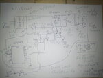
All right let's back to your circuit here it comes :

Buck for Steven.JPG


Sorry it my handwriting or drawing is not good because i drew it as fast as i could !
You need to give +15 volts to both integrated circuits to work as well . but this 15 volts won't need the current more than 150 mA so you can earn it by a simple capacitor and zener diode from main line or perhaps somewhere else .

Is the circuit clear ? any question about that ?

Good Luck :-D

- - - Updated - - -

In addition , do you have access to oscilloscope ? if yes , you should play with that potentiometer ( before you turn the 120 volt on ) but when ICs have been supplied , to achieve the frequency of 100 KHZ . you should measure frequency of pin 6 of UC3845 .
 
Awesome!!! Looks great! Let me digest it. :)

Steven

- - - Updated - - -

Awesome!!! Looks great! Let me digest it a bit. :)
Yes, I have the oscilloscope...

Steven
 

Thank you very much, Goldsmith!!!!

- - - Updated - - -

I will post oscilloscope clippings and voltage/current readings... :))))
 

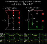
This is not intended to contradict Goldsmith's recommendation of a buck converter.
It's a theoretical concept of using a coil to reduce AC current to a load.

Screenshot:


The coil needs to be a precise value, tailored to the load. Since this is not easy to achieve, I made two layouts, showing behavior when the Henry value is low (requiring safety resistors, left), and high (allowing less current than you desire, right).

If your led strings can tolerate 2.6 A at a 50% duty cycle, then the coil value can be smaller. You may not need safety resistors.

The plain diodes are a precaution, to protect the led's from overly high reverse V.

(The capacitors are for power factor correction. They may be optional. I could be wrong as to the configuration.)
 
I have to feed them with 108V and 1.3A current (combined).

If I rectify 120V after diode bridge voltage increases to approximately 168V. I have excess of 32 volts (28V drops on LED drivers).
Hi Steven

The NSI45090JDT4G datasheet says maximum current is 160mA and maximum power dissipation is 2.7W. In your circuit, each NSI45090JDT4G carries 430mA current and dissipates 12W. Is this not a problem?

BTW, you forgot to answer Goldsmith's questions earlier.
You told your input is 120 volt AC ? and you need 32 volt ?
Now he has designed for you a 32V power supply. Look at top right corner of the circuit he gave. It says "output 32V".
 
Status
Not open for further replies.

Part and Inventory Search

Welcome to EDABoard.com

Sponsor

Back
Top