Continue to Site

Welcome to EDAboard.com

Welcome to our site! EDAboard.com is an international Electronics Discussion Forum focused on EDA software, circuits, schematics, books, theory, papers, asic, pld, 8051, DSP, Network, RF, Analog Design, PCB, Service Manuals... and a whole lot more! To participate you need to register. Registration is free. Click here to register now.

How MPPT is realized in detail

Status
Not open for further replies.

victordion

Newbie level 6
Joined
Jan 6, 2011
Messages
14
Helped
0
Reputation
0
Reaction score
0
Trophy points
1,281
Activity points
1,420
I know that when using a PV cell you need to do MPPT, but I have questions on how it is realized in detail.

Suppose we have the following configuration, the DC-DC outputs a regulated voltage.


PV cell -----> DC-DC------> Load


My question is if you do Perturb and Observe, you need to control the output voltage of the PV cell. But how it is achieved? Is it by changing the input resistance of the DC-DC? But I don't see such feasibility in any DC-DC I know so far.

Or is it realized by changing the DC-DC regulator's output voltage? In this situation the load's dissipated power will change, and then we can find a new point on PV cell's IV curve that satisfies this power demand. However, I think a DC-DC outputting regulated voltage has its output voltage programmed by external resistors, and once the circuit is built the output voltage cannot be changed on the fly.

In short, my question is what is the control knob on DC-DC when doing MPPT?
 

To implement MPPT you need a power sink, like a battery, which can accept a wide range of current without being damaged or changing voltage significantly. You can simply perturb the duty cycle of your DC-DC converter while observing the effects on PV voltage and current. The output of the converter is usually not directly regulated (except to protect the battery from overcharging).
 

You can't regulate a converter for constant output voltage (or constant current) and maimum power point at the same time. It depends on the intended converter operation and load if MPPT is feasible at all.

E.g., in case of a battery charger, the converter can operate in MPPT as long as the maximum charging current or the maximum batter voltage isn't exceeded.
 

Thanks but I still do not quite get it.

Let me put the question in another way. I read from some paper that MPPT is done by adjusting D, the duty cycle of the DC-DC converter.

Suppose we have the following circuit to use PV cell to charge a battery. And the duty cycle is D. The PV cell has an IV relation as V = f(I). The DC-DC is ideal and has no power loss.
How can do calculate the working point, e. g. I1, V1, I2, V2?
mppt.png
My way is

V2 = D*V1;
I2 = (V2 - Vb)/Rs
V1 = f(I1)
V1 * I1 = V2 * I2

Is that right?
 

Just measure the PV current and Volt. increment or decrement the D to find the maximum Power.
 

Hi every one I am also a newbie to this blog ...
I am also having quite some problems in understanding mppt concept since I chose my final year project as mppt to charge battery .....
1. If I am using 12v battery to charge , what is the output of the converter ..say buck converter ? should I hold it at a steady voltage ...and how?
2. Does output of buck converter stay constant to varying dutycycle ...? When duty cycle is varied to track mppt using p&o algorithm or incremental conductance..?
3. Can I use any algorithm(like P&O or incremental conductance) with any converter topology (say buck,sepic...etc)...
Please help ...I cannot progress my project because I am stuck with these confusions ...
Thank you ,,,,
 

P&O is easy to implement, there is a reference document on this subject from microchip. when the battery is too low the MPPT will be at best when you reach 14.3 your job is done. Then get out of MPPT and start Batt. charging Algo. as you already have current sensors installed reduced your current to a floating point value while checking the terminal voltage for not exceeding 13.8. that's all to it, If still confused then give your schematic and source code here we may be able to help. Remember one thing no body here will do your project on turn-key basis you have to do your initial homework.
And don,t forget the thank you button for any body helps you, this encourages the helper and his well to help you, so get started and don,t think too much just go ahead.
 
Understand first how a PV cell operates and secondarily what the conditions that the PV will see in the environment, such as temp variation and illumination variation as clouds go by.

PV cell is an illumination based current source that is clamped in maximum voltage level by the cell's inherent diode. There is shunt loss resistance (which for a good quality cell is minor) and series resistance (primarily due to the metal feed and resistance to cell PN body junction).

If a PV cell is left unloaded in the sun, all the generated illumination current is shunted down the inherent diode within the cell PN junction. The voltage drop will be just like a forward biased diode voltage drop. For silicon it will be 0.6 to 0.8 vdc per cell depending on how much current shunts through the cell.

If a PV cell is short circuited (or shunted with an amp meter) it will show a current based on the illumination level. The illumination current generated has a minor dependence on temperature so this amp meter shunt make a good illumination level indicator.

MPPT point is a load on the cell (or series of cells) that allows the highest possible voltage across the PV cell while allowing only a small amount of illumination generated current (2-3%) to be shunted down the cell's inherent diode. This yields the best V x I product output or maximum power for a given level of illumination generated cell current.

Since the inherent cell diode voltage drop is a function of temperature, just like a regular diode, MPPT optimum loaded voltage point will vary depending on what is the temp of the cell. As cell get hotter in the sun it produces less power (for same illumination level) since the cell inherent diode voltage will be lower as temperature goes up. Neglecting cell shunt resistance, the series resistance in the PV circuit path will have more voltage drop, the more the output illumination current is.

Now to switching power supplies. Most switching power supplies are output voltage regulated switching power supplies (perhaps with a maximum output current limit for protection) that also require a relatively low impedance input source, i.e. a voltage source for their input. Hook this type of a buck or boost switcher to a high impedance current source, like a PV panel, and they will likely result in a switcher that oscillates with unpredictable results.

A switching power converter for a PV panel must be regulated by input voltage and current to load the PV array for maximum power draw, as well as secondary feedback from output voltage and current to protect the battery from overcharging or excessive charging current. When the battery side reaches maximum charge voltage or current the switcher will no longer be operated in MPPT mode.

Assuming the output power from the MPPT switcher is not limited, then the MPPT regulation is solely a function of allowing the switcher to draw more current from the PV array (increase the load on PV array) to point where the voltage starts to drop. A simple MPPT switcher can just regulate based on input voltage but this does not take into account PV temp variation or series resistance voltage drop to PV cells. This is sort of equivalent to saying first order approximation for a silicon diode voltage drop is always 0.6 vdc. Normal MPPT voltage for a moderately sun warmed PV cell is around 0.52 vdc per cell. If you are in a hot desert it may be as low as 0.42 vdc for silicon. If you are in a cold environment it might be as high as 0.68 vdc per cell. A more sophisticated MPPT controller will adjust for this by searching out the best V x I product.

This MPPT algorithm is not as simple as it might sound given the changing environment of clouds passing by on a partly cloudy day and the fact the cell cools down when shaded by clouds and heats up when in the clear sun. Just about all MPPT controller do a load 'hunting' process to search for the best loading to yield best V x I product. Again, not as easy as it might seem since this hunting process, by default, means the cell is not being operated at it maximum V x I product during some of the time spent in the hunting process. The amount of time spent hunting can degrade the overall average MPPT power delivered.

Here is the frustration for the MPPT hunting algorithm: Just when you hunted your way to find the best V * I product, the sun again dips behind a cloud and the illumination generated current drops significantly. If the switcher does not react quickly to lighten the load on the PV array the input voltage will drop like a rock. Input voltage is detected to quickly react. Also realize the cooling down of the cells in the cloud shaded condition and the heating when sun re-appears occurs at a much slower rate then rather quick illumination level change. So you must decide when is 'good enough'. Hunt too much and you lose the MPPT overall benefit.

A single parameter sense feedback control system is difficult for most folks to achieve proper loop stability of the switcher. The PV MPPT controller is a multi-sensed, multiple loop feedback control system. A very complicated design task.

MPPT controller usually do not justify themselves for PV arrays less then 1000 watts. Just a simple PWM controller is more cost effect for smaller power arrays. PWM controller is nothing but an ON-OFF chopping switch allowing the PV illumination current to pass directly to batteries or not. This regulates the maximum average charge current to battery and turns off (or low duty cycles) when battery full charge voltage is reached. PV array must always be greater then maximum charge state battery voltage, but it is desireable to not be excessively higher, as PV load voltage when switch is ON is always going to drop to battery voltage.
 
Last edited:
Thanks for the help guys.....
As naseerak said, I started doing the project and I am able to sense voltage ,current and calculate power from pv as well as battery...
now I have used a pot with the atmega128 to control the duty cycle of 62.5khz pwm.....So I can manually hunt for the mpp without algorithm .....
Everything is pretty much done .....The problem is with the sepic converter ....I am not getting an output greater than 1.5-2v ,If I am getting some output,the mosfet IRF540 heats up so much ...I already wasted 3 mosfets...I am really stuck with the sepic converter....I am using Ir2110 to drive the mosfet....
I am giving about 11v to IR2110 to drive the mosfet....I have confirmed the waveforms in oscilloscope as well....
If there is 5v from microcontroller,the IR2110 gives around 10v...

So if I vary pwm of microcontroller from 0-100% gradually ,[the multimeter shows 0-5v varying with all the analog signals in between and the output of IR2110 varies from 0-10v in multimeter]...which confirms the working of mosfet driver....

The problem is ,when I connect the driver to the gate of IRF540 and if I vary dutycycle from 0-100%,the gate voltage in multimeter only shows a max of 4.7v.....
What is the problem ...?
Guys if only I can get the sepic converter working ,I can show them mppt....
There is only about 20 days to get the project finished....Please provide some suggestion...
 

Attachments

  • Screenshot 2014-03-01 14.39.16.png
    Screenshot 2014-03-01 14.39.16.png
    267.9 KB · Views: 141

Instead of a simulation, show the real circuit and actual measured waveforms.
 

Thanks, I get an idea about the nature of the problems.
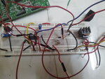
- driving IRF540 from IR2110 on breadboard and through long wires possibly doesn't work
- self made 60 µH inductors might be unsuitable (core saturation?). What's the core type?
- is output diode fast type?
- input and output capacitors have unlikely sufficient low ESR
- additional problems might be brought up by the stripboard design. (We didn't yet see the bottom side).

Viewing the voltage waveforms in the Sepic circuit (Vin, Vgs, Vds, etc.) can tell more bout the real situation.
 
60uH it is a ferrite core inductor....not actually made by me...but by some one who is in the field of designing of inductors....

input and output capacitors are 220uF...which one to put then ?

should the capacitor in between the two inductors be non polarized ....?when I put 150pF in between them ,the mosfet was smoking ....when i simulated the circuit with 150pF in proteus ,there were high voltage spikes of about 100v in the mosfet drain....
And when I connnect the solar panel which would be giving 19v appx to the input of the sepic ,the voltage would fall to 2.5v or less....but there would be a healthy current going into the sepic of about 1.2 amps...I am using a 20w panel....
The output diode is FR304...it can handle upto 2amps I guess and it is fast recovery diode....
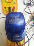
bread board through long wires...??? I am supplying Ir2110 about 10v-13v from an adapter which is rated max of 1000mA current....
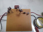
Strip board design ......
Oh my....so many problems ....if I get a proper output ,and everything works well,I am going to make a tutorial for newbies who are going to take up his kind of project so that it might be useful for ....
At this time I cant show you waveforms cause I dont have an osilloscope ....I will post the waveforms when Im in college.....
Thanks for the quick reply.....
I will post the bottom side too....

Go green ,Go solar!!!..

- - - Updated - - -

I am using low side mosfet driver from Tahmid's blog
http://tahmidmc.blogspot.in/2013/01/using-high-low-side-driver-ir2110-with.html
This the circuit Im using to drive the mosfet.....

- - - Updated - - -

core saturation.....in inductor ...??I am guessing all the current is flowing through the inductor which is across....I dont know what kind of capacitor it is in between the inductors ....I asked for 1uH and 2.2uH without polarity,and i hooked them in parallel to get more capacitance ....
 

Attachments

  • 20140301_180043.jpg
    20140301_180043.jpg
    2.2 MB · Views: 127
  • 20140301_180824.jpg
    20140301_180824.jpg
    2.2 MB · Views: 122
  • IR2110 - 5.png
    IR2110 - 5.png
    24.9 KB · Views: 132
FR304 is O.K.

I realized that the IRF540 is placed on the breadboard, too. That's even worse in my opinion. You can't make a 50 or 100 kHz switcher as wire entanglement.

Regarding inductors, you should ask for the saturation current calculation. Maybe I'm wrong and they can still work for the present circuit.

The capacitors didn't look like 220 µF low ESR at first sight, but maybe they are.

The Sepic capacitor polarity can be derived from the average voltage level at both sides. The average voltage across the output inductor must be zero, thus it's the negative side. Capacitor polarity seems to be wrong in the previous photo.

It's hard to decide which of the discussed points makes your design fail in a first order and if it can work at least with minimal performance after fixing this problem.

Layout-wise, I would suggest a stripboard with Sepic circuit, IRF540 and IR2110 near to each other. Good ground connection and supply bias directly at the IR2110.
 
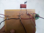
sorry for the wrong pic ....the bottom side shows two big capacitors which do not have any polarity....
225J250v and 105J250v is written on the capacitors that are in parallel.....the other pic shows two electrolytic capacitors 22uF in antiparallel..I was just trying out different things....

- - - Updated - - -

Is my design for sepic ok ...? I referred coilcraft.com...what do you suggest me to do ??what other components can I try out with..?I am connecting the micrcontroller ground , sepic converter ground ,the solar panel -ve and the mosfet source together as ground ....is it right???
 

Just use a simple buck converter with a P-channel mosfet to make the drive easy.
 
The buck converter demands that I use mosfet in the high side......so I have to have ir2110 in high side drive.....
Can anyone tell me why the mosfet is heating up so much and getting smoke....??..
Are my connections wrong...?
Is buck converter easier than sepic..?
Are there any other mosfets can I use...?
I want to know why the gate voltage of mosfet does not go beyond 4.7v ....when it can go upto 10v without connecting it with mosfet gate (I.e, from ir2110 output)..
 

But you are driving your mosfet from the lower out put seeing the proteus image
 

I did not understand..
 

Status
Not open for further replies.

Part and Inventory Search

Welcome to EDABoard.com

Sponsor

Back
Top