cupoftea
Advanced Member level 5
Hi,
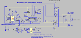
The attached shows a Full Bridge with Synchronous Rectifiers. (LTspice and PNG)
48Vin, 12Vout 200Wout, 117kHz.
At 3ms in the LTspice sim, the load gets suddenly switched out from full load to no load. As the inductor current falls,
it then reverses, -whilst it is in reverse in the synchronous FET, the synch FET is then turned OFF. This is "breaking an
inductive current"...not just some little stray inductive current, but the inductive current in the power inductor!
These overvoltages are so high that they overvoltage the synch FETs and their paralleled diodes.
It may be said that the LTC3901 offers reverse current sensing in the synchronous FETs, and that it would switch them off
before this current got too high. However, this is not acceptable. The signal from any sense resistor would be very small, and
drowned in noise at low levels of reversing current.
In any case, by the time the power inductor current has actually gone into reverse, its way too late to switch off the sync rect FETs.
May i ask Why has this chip (LTC3901) been manufactured?
It is unsuitable for purpose. It doesnt even have a shutdown pin
so that the synch rects can be turned off as the inductor current falls towards zero.